6
SMT Assembly
passes through one or more
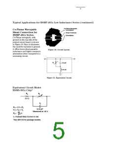
Assembly Information
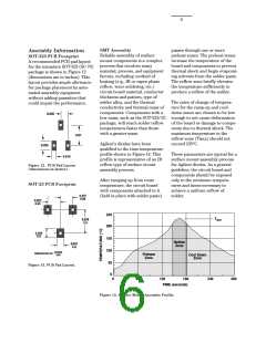
SOT-323 PCB Footprint
Reliable assembly of surface
mount components is a complex
process that involves many
material, process, and equipment
factors, including: method of
heating (e.g., IR or vapor phase
reflow, wave soldering, etc.)
circuit board material, conductor
thickness and pattern, type of
solder alloy, and the thermal
conductivity and thermal mass of
components. Components with a
preheat zones. The preheat zones
increase the temperature of the
board and components to prevent
thermal shock and begin evaporat-
ing solvents from the solder paste.
The reflow zone briefly elevates
the temperature sufficiently to
produce a reflow of the solder.
A recommended PCB pad layout
for the miniature SOT-323 (SC-70)
package is shown in Figure 12
(dimensions are in inches). This
layout provides ample allowance
for package placement by auto-
mated assembly equipment
without adding parasitics that
could impair the performance.
The rates of change of tempera-
ture for the ramp-up and cool-
down zones are chosen to be low
0.026
low mass, such as the SOT-323/-23 enough to not cause deformation
package, will reach solder reflow
temperatures faster than those
with a greater mass.
of the board or damage to compo-
nents due to thermal shock. The
maximum temperature in the
0.07
reflow zone (T
) should not
MAX
Agilent’s diodes have been
qualified to the time-temperature
profile shown in Figure 14. This
profile is representative of an IR
reflow type of surface mount
assembly process.
exceed 235°C.
0.035
These parameters are typical for a
surface mount assembly process
for Agilent diodes. As a general
guideline, the circuit board and
components should be exposed
only to the minimum tempera-
tures and times necessary to
achieve a uniform reflow of
solder.
0.016
Figure 12. PCB Pad Layout
(dimensions in inches).
After ramping up from room
temperature, the circuit board
with components attached to it
(held in place with solder paste)
SOT-23 PCB Footprint
0.037
0.95
0.037
0.95
250
200
TMAX
0.079
2.0
0.035
0.9
150
Reflow
Zone
0.031
0.8
100
inches
DIMENSIONS IN
mm
Preheat
Zone
Cool Down
Zone
50
0
Figure 13. PCB Pad Layout.
0
60
120
180
240
300
TIME (seconds)
Figure 14. Surface Mount Assembly Profile.

 AGILENT [ AGILENT TECHNOLOGIES, LTD. ]