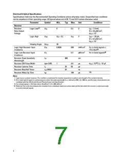
Electrical & Optical Specifications
Specifications hold over the Recommended Operating Conditions unless otherwise noted. Unspecified test conditions
can be anywhere in their operating range. All typical values are at 25 °C and 3.3 V unless otherwise noted.
Parameter
Symbol
Min.
Typ. Max.
Unit
Conditions
Receiver
[7]
Receiver
Data Output
Voltage
Logic Low
V
0
-
-
0.4
V
I
OL
= 1.0 mA,
OL
2
EI ≥ 3.6 µW/cm ,
θ
≤ 15°
1/2
Logic High
V
OH
V
– 0.2
V
CC
V
I
= –20 µA,
CC
OH
2
EI ≤ 0.3 µW/cm ,
≤ 15°
θ
1/2
Viewing Angle 2θ
30
0.0036
°
1/2
2
Logic High Receiver Input
Irradiance
EI
500
0.3
mW/cm
For in-band signals ≤
H
[8]
115.2 kb/s
2
[8]
Logic Low Receiver Input
Irradiance
EI
µW/cm
For in-band signals
L
Receiver Peak Sensitivity
Wavelength
λ
880
nm
P
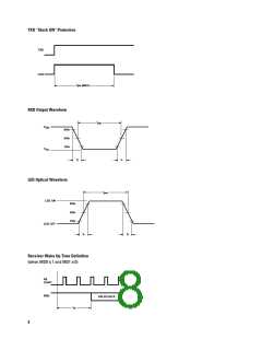
Receiver SIR Pulse Width
Receiver Latency Time
Receiver Rise/Fall Times
Receiver Wake Up Time
tpw (SIR)
1
4.0
50
µs
µs
ns
µs
θ1/2 ≤ 15°[9], CL= 10 pF
t
t
t
20
25
L
(RXD)
r/f
W
[10]
100
Notes:
7. Logic Low is a pulsed response. The condition is maintained for duration dependent on pattern and strength of the incident intensity.
8. An in-band optical signal is a pulse/sequence where the peak wavelength, lp, is defined as 850 ≤ lp ≤ 900 nm, and the pulse characteristics are
compliant with the IrDA Serial Infrared Physical Layer Link Specification.
9. For in-band signals ≤ 115.2 kb/s where 3.6 µW/cm2 ≤ EI ≤ 500 mW/cm2.
10. Wake Up Time is the time between the transition from a shutdown state to an active state and the time when the receiver is active and ready
to receive infrared signals.
7

 AGILENT [ AGILENT TECHNOLOGIES, LTD. ]