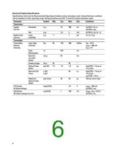
Electrical & Optical Specifications
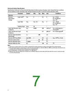
Specifications hold over the Recommended Operating Conditions unless otherwise noted. Unspecified test conditions
can be anywhere in their operating range. All typical values are at 25 °C and 3.3 V unless otherwise noted.
Parameter
Symbol
Min.
Typ.
Max.
Unit
Conditions
Transceiver
Supply
Current
Shutdown
Idle
I
10
200
nA
V (TXD) ≤ V or
CC1
I
IL
V (TXD) ≥ V
I
IH
I
I
2.5
5
1
mA
V (TXD) ≤ V , EI = 0
I IL
CC2
L/H
Digital Input
Current
Logic
Low/High
–1
50
µA
0 ≤ V ≤ V
I CC
Transmitter
Transmitter
Radiant
Logic High
Intensity
EI
120
400
mW/sr
V
= 3.0 V
= 200 mA
H
IH
I
LEDA
Intensity
θ
≤ 15°
1/2
Peak
Wavelength
λ
875
35
nm
nm
P
Spectral
Line Half
Width
∆λ
1/2
Viewing Angle
2θ
30
60
°
1/2
Optical Pulse
Width
tpw (EI)
1.5
1.6
20
1
1.8
µs
tpw(TXD) = 1.6 µs at
115.2 kb/s
Rise and Fall
Times
t (EI),
40
50
ns
tpw(TXD) = 1.6 µs at
115.2 kb/s
r
t (EI)
f
t
(TXD) = 10 ns
r/f
Maximum
Optical Pulse
Width
tpw (max)
µs
TXD pin stuck high
LED Anode
On State Voltage
V
ON
(LEDA)
2.4
V
I
= 200 mA,
LEDA
V (TXD) ≥ V
I IH
LED Anode
Off State Leakage Current
I
(LEDA)
LK
100
nA
V
= V =5.25 V,
LEDA CC
V (TXD) ≤ V
I IL
6

 AGILENT [ AGILENT TECHNOLOGIES, LTD. ]