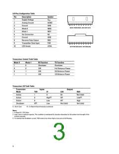
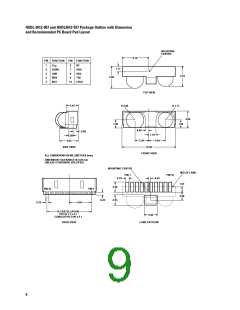
I/O Pins Configuration Table
Pin
1
Description
Supply Voltage
Analog Ground
Ground
Symbol
V
CC
2
AGND
GND
MD0
MD1
NC
10
9
8
7
6
5
4
3
2
1
3
BACK VIEW (HSDL-3612-007/-037)
4
Mode 0
5
Mode 1
6
No Connection
Ground
7
GND
RXD
TXD
8
Receiver Data Output
Transmitter Data Input
LED Anode
9
10
9
8
7
6
5
4
3
2
1
10
LEDA
BOTTOM VIEW (HSDL-3612-008/-038)
Transceiver Control Truth Table
Mode 0
Mode 1
RX Function
TX Function
1
0
0
1
0
0
1
1
Shutdown
SIR
Shutdown
Full Distance Power
2/3 Distance Power
1/3 Distance Power
SIR
SIR
Transceiver I/O Truth Table
Transceiver
Mode
Inputs
Outputs
TXD
EI
LED
RXD
Active
1
0
0
X
On
Not Valid
[1]
[2]
Active
High
Low
Low
Off
Low
Active
Off
High
[3]
Shutdown
X
Not Valid
Not Valid
X = Don’t Care
EI = In-Band Infrared Intensity at detector
Notes:
1. In-Band El ≤ 115.2 kb/s.
2. Logic Low is a pulsed response. The condition is maintained for duration dependent on the pattern and strength of the
incident intensity.
3. To maintain low shutdown current, TXD needs to be driven high or low and not left floating.
3

 AGILENT [ AGILENT TECHNOLOGIES, LTD. ]