Electrical Specifications (T = 25˚C)
A
Parameter
Symbol
Min.
–
Typ.
1.2
50
–
Max.
1.4
250
100
–
Units
V
Test Conditions
Forward Voltage
Terminal Capacitance
Collector Dark Current
V
F
I = ±20 mA
F
C
t
–
pF
nA
V
V = 0, f = 1 kHz
I
–
V = 20 V, I = 0
CE F
CEO
Collector-Emitter Breakdown Voltage BV
Emitter-Collector Breakdown Voltage BV
35
6
–
I = 0.1 mA, I = 0
C F
CEO
–
–
V
I = 10 µA, I = 0
E F
ECO
Collector Current
I
0.2
20
–
–
3
mA
%
I = ±1 mA,
F
C
[2]
Current Transfer Ratio
CTR
–
300
0.2
–
V = 5 V
CE
Collector-Emitter Saturation Voltage
Isolation Resistance
V
0.1
1 x 10
V
I = ±20 mA, I = 1 mA
F
CE(sat)
iso
C
10
11
R
5 x 10
Ω
DC 500 V
40 ~ 60% R.H.
Floating Capacitance
Cut-off Frequency
C
–
0.6
80
1
–
pF
V = 0, f = 1 MHz
f
f
15
kHz
V = 5 V, I = 2 mA
CE C
c
R = 100 Ω, –3 dB
L
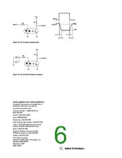
Response Time (Rise)
Response Time (Fall)
t
–
–
4
3
18
18
µs
µs
V = 2 V, I = 2 mA,
CE C
r
t
f
R = 100 Ω
L
Rank Mark
A
CTR(%)
50 ~ 150
20 ~ 300
Conditions
I = ±1 mA,
F
No Mark
V
CE
= 5 V,
T = 25˚C
A
Notes:
1. Isolation voltage shall be measured using the following method:
(a) Short between anode and cathode on the primary side and between collector and emitter
on the secondary side.
(b) The isolation voltage tester with zero-cross circuit shall be used.
(c) The waveform of applied voltage shall be a sine wave.
IC
IF
2.
CTR =
x 100%
60
50
40
30
20
10
200
150
100
50
6
5
4
3
2
1
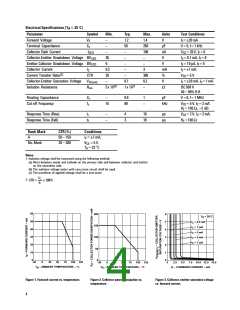
T
= 25°C
A
I
I
I
I
I
= 0.5 mA
= 1 mA
= 3 mA
= 5 mA
= 7 mA
C
C
C
C
C
0
0
0
0
-30
0
25
50
75
100 125
-30
0
25
50
75
100 125
2.5
I – FORWARD CURRENT – mA
F
5.0
7.5 10.0 12.5 15.0
T
– AMBIENT TEMPERATURE – °C
T
– AMBIENT TEMPERATURE – °C
A
A
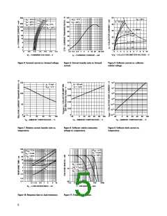
Figure 1. Forward current vs. temperature.
Figure 2. Collector power dissipation vs.
temperature.
Figure 3. Collector-emitter saturation voltage
vs. forward current.
4

 AGILENT [ AGILENT TECHNOLOGIES, LTD. ]