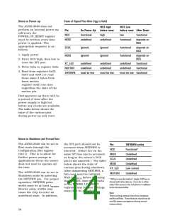
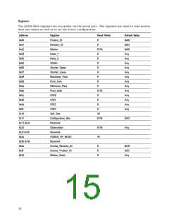
Notes on Power-up
State of Signal Pins After V is Valid
DD
The ADNS-3040 does not
perform an internal power up
self-reset; the
POWER_UP_RESET register
must be written every time
power is applied. The
appropriate sequence is as
follows:
NCS high
before reset
NCS Low
before reset After Reset
Pin
On Power-Up
functional
NCS
MISO
high
low
functional
undefined
undefined
functional
depends on
NCS
SCLK
MOSI
ignored
ignored
ignored
ignored
functional
functional
depends on
NCS
1. Apply power
depends on
NCS
2. Drive NCS high, then low to
reset the SPI port
XY_LED
MOTION
SHTDWN
undefined
undefined
must be low
undefined
undefined
must be low
undefined
undefined
functional
functional
3. Write 0x5a to register 0x3a
4. Read from registers 0x02,
0x03 and 0x04 (or read
these same 3 bytes from
burst motion
must be low functional
register 0x42) one time
regardless the state of the
motion pin.
During power-up there will be
a period of time after the
power supply is high but
before any clocks are available.
The table below shows the
state of the various pins
during power-up and reset.
Notes on Shutdown and Forced Rest
The ADNS-3040 can be set in
Rest mode through the
Configuration_Bits register
(0x11). This is to allow for
further power savings in
applications where the sensor
does not need to operate all
the time.
the SPI port should not be
accessed when SHTDWN is
Pin
SHTDWN active
Functional*
Undefined
NCS
asserted. (Other ICs on the
same SPI bus can be accessed,
as long as the sensor’s NCS
pin is not asserted.) The table
below shows the state of
various pins during shutdown.
After deasserting SHTDWN, a
full reset must be initiated.
MISO
SCLK
Undefined
MOSI
Undefined
XY_LED
MOTION
Low current
Undefined
The ADNS-3040 can be set in
Shutdown mode by asserting
the SHTDWN pin. For proper
operation, SHTDWN pulse
Wait t
before accessing
WAKEUP
* NCS pin must be held to 1 (high) if SPI bus is
shared with other devices. It can be in either
state if the sensor is the only device in addition
to the microcontroller.
the SPI port, then write 0x5A
to the POWER_UP_RESET
register. Any register settings
must then be reloaded.
width must be at least t
.
STDWN
Shorter pulse widths may
cause the chip to enter an
undefined state. In addition,
Note:
There are long wakeup times from shutdown
and forced Rest. These features should not be
used for power management during normal
mouse motion.
14

 AGILENT [ AGILENT TECHNOLOGIES, LTD. ]