Data Sheet
July 2000
LU6612
FASTCAT Single-FET for 10Base-T/100Base-TX
Timing Characteristics (Preliminary)
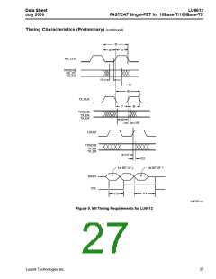
Table 25. MII Management Interface Timing (25 pF Load)
Name
Parameter
Min
Typ
Max
Unit
t1
t2
t3
t4
t5
t6
MDIO Valid to Rising Edge of MDC (setup)
Rising Edge of MDC to MDIO Invalid (hold)
MDC Falling Edge to MDIO Valid (prop. delay)
MDC High*
10
10
0
—
—
—
—
40
—
—
—
ns
ns
ns
ns
ns
ns
—
—
40
80
200
200
400
MDC Low*
MDC Period*
* When operating MDC above 6.25 MHz, MDC must be synchronous with LSCLK and have a setup time of 15 ns and a hold time of 5 ns,
with respect to LSCLK.
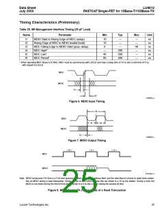
MDC
MDIO
t1
t2
5-4959(F).a
Figure 6. MDIO Input Timing
t6
MDC
t5
t4
MDIO
t3
5-4960(F).c
Figure 7. MDIO Output Timing
< R >
< Z >
< O >
MDC
MDIO
5-5312(F).r1
Note: MDIO turnaround (TA) time is a 2-bit time spacing between the register address field, and the data field of a frame to avoid drive conten-
tion on MDIO during a read transaction. During a write to the LU6612, these bits are driven to a 10 by the station. During a read, the
MDIO is not driven during the first bit time and is driven to a 0 by the LU6612 during the second bit time.
Figure 8. MDIO During TA (Turnaround) of a Read Transaction
Lucent Technologies Inc.
25

 AGERE [ AGERE SYSTEMS ]