Data Sheet
AD5940
THEORY OF OPERATION
The main blocks of the AD5940 are as follows:
•
Programmable switch matrix. The input switching of the
AD5940 allows full configurability in the connections of
the external sensors (see the Programmable Switch Matrix
section).
Programmable sequencer (see the Sequencer section).
SPI interface.
Waveform generator designed to create sinusoid and
trapezoid waveforms up to 200 kHz (see the Waveform
Generator section).
Interrupt sources that output to a GPIOx pin to alert the
host controller that an interrupt event occurred (see the
Interrupts).
•
Low power, dual-output, string DAC used to set the sensor
bias voltage and low frequency excitation. Supports
chronoamperometric and voltammetry electrochemical
techniques.
•
•
•
•
•
•
Low power potentiostat that applies the bias voltage to the
sensor.
Low power TIA that performs low bandwidth current
measurements.
High speed DAC and amplifier designed to generate
excitation signals for impedance measurements up to
200 kHz.
•
•
Digital inputs/outputs (see the Digital Inputs/Outputs
section).
•
•
High speed TIA that supports wider signal bandwidth
measurements.
High performance ADC circuit (see the High Performance
ADC Circuit section).
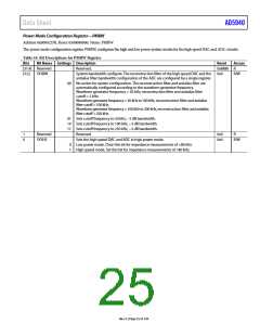
CONFIGURATION REGISTERS
Table 8. Configuration Registers Summary
Address
Name
Description
Reset
Access
R/W
R/W
0x00002000
0x000022F0
AFECON
PMBW
AFE configuration register
Power modes configuration register
0x00080000
0x00088800
Configuration Register—AFECON
Address 0x00002000, Reset: 0x00080000, Name: AFECON
Table 9. Bit Descriptions for AFECON Register
Bits
Bit Name
Settings Description
Reset Access
[31:22] Reserved
Reserved.
0x0
0x0
R
21
DACBUFEN
Enables the dc DAC buffer. This bit enables the buffer for the high impedance
output of the dc DAC.
R/W
0
1
Disables the dc DAC buffer.
Enables the dc DAC buffer.
20
19
DACREFEN
High speed DAC reference enable.
Reference disable. Clear to 0 to disable the high speed DAC reference.
Reference enable. Set to 1 to enable the high speed DAC reference.
0x0
0x1
R/W
R/W
0
1
ALDOILIMITEN
Analog low dropout (LDO) regulator current limiting. This bit enables AFE
analog LDO buffer current limiting. If enabled, this feature limits the current
drawn from the battery while charging the capacitor on the AVDD_REG pin.
0
1
Analog LDO buffer current limiting enabled.
Analog LDO buffer current limiting disabled.
Reserved.
[18:17] Reserved
0x0
0x0
R
R/W
16
SINC2EN
ADC output 50 Hz/60 Hz filter enable. This bit enables the 50 Hz/60 Hz supply
rejection filter.
0
1
Supply rejection filter disabled. Disables sinc2 (50 Hz/60 Hz digital filter).
Disable this bit for impedance measurements.
Supply rejection filter enabled. Enables sinc2 (50 Hz/60 Hz digital filter).
15
DFTEN
DFT hardware accelerator enable. This bit enables the DFT hardware
acceleration block.
0x0
R/W
0
1
DFT hardware accelerator disabled.
DFT hardware accelerator enabled.
Rev. 0 | Page 23 of 130

 ADI [ ADI ]