Data Sheet
AD5940
APPLICATIONS INFORMATION
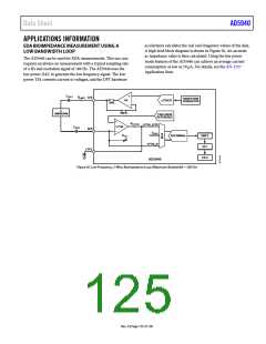
EDA BIOIMPEDANCE MEASUREMENT USING A
LOW BANDWIDTH LOOP
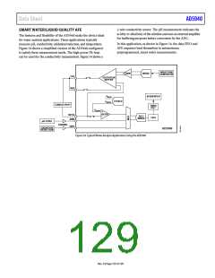
accelerators calculates the real and imaginary values of the data.
A high level block diagram is shown in Figure 50. An accurate
ac impedance value is then calculated. Using the low power
mode features of the AD5940 can achieve an average current
consumption as low as 70 μA. For details, see the AN-1557
Application Note.
The AD5940 can be used for EDA measurements. This use case
requires an always on measurement with a typical sampling rate
of 4 Hz and excitation signal of 100 Hz. The AD5940 uses the
low power DAC to generate the low frequency signal. The low
power TIA converts current to voltages, and the DFT hardware
C
+
ISO1
R
CE0
LIMIT
WAVEFORM
GENERATOR
PA
LPDAC0
SW2
–
Z
SW10
UNKNOWN
PRECISION
REFERENCE
+
R
FILTER
LPTIA_LPF0
LPTIA
C
ISO2
SE0
–
V
CEO
R
ADC/800kHz
SINC3
DFT
TIA
LPTIA_N
LPF0
FIFO
AD5940
Figure 50. Low Frequency, 2-Wire, Bioimpedance Loop (Maximum Bandwidth = 300 Hz)
Rev. 0 | Page 125 of 130

 ADI [ ADI ]