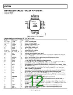
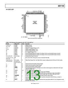
ADV7180
INPUT CONFIGURATION
Table 10. ADV7180 LQFP-64 INSEL[3:0]
There are two key steps for configuring the ADV7180 to
correctly decode the input video.
INSEL[3:0]
Video Format
Composite
Composite
Composite
Composite
Composite
Composite
Y/C (S-video)
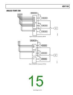
Analog Input
CVBS → AIN1
CVBS → AIN2
CVBS → AIN3
CVBS → AIN4
CVBS → AIN5
CVBS → AIN6
Y → AIN1
0000
0001
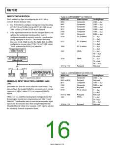
1. Use INSEL[3:0] to configure routing and format decoding
(CVBS, Y/C, or YPrPb). For the ADV7180 LQFP-64, see
Table 10. For ADV7180 LFCSP-40, see Table 11.
0010
0011
0100
2. If the input requirements are not met using the INSEL[3:0]
options, the analog input muxing section must be
0101
0110
configured manually to correctly route the video from the
analog input pins to the ADC. The standard definition
processor block, which decodes the digital data, should be
configured to process either CVBS, Y/C, or YPrPb format.
This is performed by INSEL[3:0] selection.
C → AIN4
0111
1000
1001
Y/C (S-video)
Y/C (S-video)
YPrPb
Y → AIN2
C → AIN5
Y → AIN3
C → AIN6
CONNECT ANALOG VIDEO
SIGNALS TO ADV7180.
Y → AIN1
Pb → AIN4
Pr → AIN5
SET INSEL[3:0] TO CONFIGURE
VIDEO FORMAT. USE PREDEFINED
FORMAT/ROUTING.
1010
YPrPb
Y → AIN2
Pr → AIN6
Pb → AIN3
Not used
NO
1011 to 1111
Not used
YES
LQFP-64
LFCSP-40
CONFIGURE ADC INPUTS USING
MANUAL MUXING CONTROL BITS:
MUX_0[3:0], MUX_1[3:0], MUX_2[3:0].
SEE TABLE 12.
Table 11. ADV7180 LFCSP-40 INSEL[3:0]
REFER TO
TABLE 10
REFER TO
TABLE 11
INSEL[3:0]
Video Format
Composite
Not used
Composite
Composite
Not used
Analog Input
CVBS → AIN1
Not used
Figure 11. Signal Routing Options
0000
0001 to 0010
0011
INSEL[3:0], INPUT SELECTION, ADDRESS 0x00
[3:0]
CVBS → AIN2
CVBS → AIN3
Not used
0100
The INSEL bits allow the user to select the input format. They
also configure the standard definition processor core to process
composite (CVBS), S-video (Y/C), or component (YPrPb)
format.
0101
0110
Y/C (S-video)
Y → AIN1
C → AIN2
Not used
0111 to 1000
1001
Not used
YPrPb
INSEL[3:0] has predefined analog input routing schemes that
do not require manual mux programming (see Table 10 and
Table 11). This allows the user to route the various video signal
types to the decoder and select them using INSEL[3:0] only.
The added benefit is that if, for example, CVBS input is selected,
the remaining channels are powered down.
Y → AIN1
Pr → AIN3
Pb → AIN2
Not used
1010 to 1111
Not used
Rev. A | Page 16 of 112

 ADI [ ADI ]