ADV7180
ANTIALIASING FILTERS
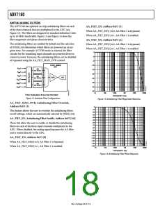
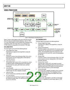
The ADV7180 has optional on-chip antialiasing filters on each
of the three channels that are multiplexed to the ADC (see
Figure 12). The filters are designed for standard definition video
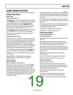
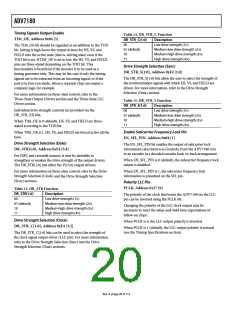
up to 10 MHz bandwidth. Figure 13 and Figure 14 show the
filter magnitude and phase characteristics.
AA_FILT_EN, Address 0xF3 [1]
When AA_FILT_EN[1] is 0, AA Filter 2 is bypassed.
When AA_FILT_EN[1] is 1, AA Filter 2 is enabled.
AA_FILT_EN, Address 0xF3 [2]
The antialiasing filters are enabled by default and the selection
of INSEL[3:0] determines which filters are powered up at any
given time. For example, if CVBS mode is selected, the filter
circuits for the remaining input channels are powered down to
conserve power. However, the antialiasing filters can be disabled
or bypassed using the AA_FILT_MAN_OVR control.
When AA_FILT_EN[2] is 0, AA Filter 3 is bypassed.
When AA_FILT_EN[2] is 1, AA Filter 3 is enabled.
0
–4
–8
–12
–16
–20
–24
–28
–32
–36
10-BIT, 86MHz
ADC
A
A
A
1
2
IN
IN
IN
AA
FILTER 1
3
1
AA
FILTER 2
SHA
A/D
A
4
5
6
IN
IN
IN
1
1
A
A
AA
FILTER 3
1k
10k
100k
1M
10M
100M
1
ONLY AVAILABLE IN 64-LEAD PACKAGE
FREQUENCY (Hz)
Figure 12. Antialias Filter Configuration
Figure 13. Antialiasing Filter Magnitude Response
AA_FILT_MAN_OVR, Antialiasing Filter Override,
Address 0xF3 [3]
0
–10
–20
This feature allows the user to override the antialiasing filters
on/off settings, which are automatically selected by INSEL[3:0].
–30
–40
AA_FILT_EN, Antialiasing Filter Enable, Address 0xF3 [2:0]
–50
–60
These bits allow the user to enable or disable the antialiasing
filters on each of the three input channels multiplexed to the
ADC. When disabled, the analog signal bypasses the AA filter
and is routed directly to the ADC.
–70
–80
–90
–100
–110
–120
–130
–140
–150
AA_FILT_EN, Address 0xF3 [0]
When AA_FILT_EN[0] is 0, AA Filter 1 is bypassed.
When AA_FILT_EN[0] is 1, AA Filter 1 is enabled.
1k
10k
100k
1M
10M
100M
FREQUENCY (Hz)
Figure 14. Antialiasing Filter Phase Response
Rev. A | Page 18 of 112

 ADI [ ADI ]