AD8325
Differential Inputs
Installing the Visual Basic Control Software
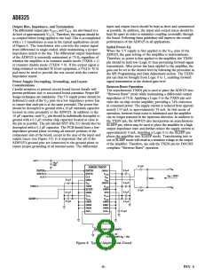
The AD8325-EVAL evaluation board may be driven with a
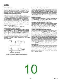
differential signal in one of two ways. A transformer may be
used to convert a single-ended signal to differential, or a differ-
ential signal source may be used. Figure 7 and the following
paragraphs describe each of these methods.
To install the “CABDRIVE_25” evaluation board control soft-
ware, close all Windows applications and then run “SETUP.EXE”
located on Disk 1 of the AD8325 Evaluation Software. Follow
the on-screen instructions and insert Disk 2 when prompted to
do so. Enter the path of the directory into which the software
will be installed and select the button in the upper left corner to
complete the installation.
Single-Ended-to-Differential Input (Figure 7, Option 1)
A TOKO 617DB-A0070 1:1 transformer is preinstalled in the
T3 location of the evaluation board. Install 0 Ω chip resistors at
R14, R15, and R20, and leave R16 through R19 open. For
50 Ω differential input impedance, install a 51.1 Ω resistor at R13.
For 75 Ω differential input impedance, use a 78.7 Ω resistor.
In this configuration, the input signal must be applied to the
VIN+ port of the evaluation board. For input impedances other
than 50 Ω or 75 Ω, the correct value for R13 can be calculated
using the following equation.
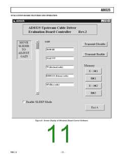
Running the Software
To invoke the control software, go to START -> PROGRAMS
-> CABDRIVE_25, or select the AD8325.EXE icon from the
directory containing the software.
Controlling the Gain/Attenuation of the AD8325
The slide bar controls the AD8325’s gain/attenuation, which is
displayed in dB and in V/V. The gain scales at 0.7526 dB per
LSB with the valid codes being from decimal 0 to 79. The gain
code (i.e., position of the slide bar) is displayed in decimal, binary,
and hexadecimal (see Figure 8).
Desired Input Impedance = (R13ꢀ1600)
Differential Input (Figure 7, Option 2)
If a differential signal source is available, it may be applied
directly to both the VIN+ and VIN– input ports of the evaluation
board. In this case, 0 Ω chip resistors should be installed at
locations R16 through R19, and R14, R15, and R20 should be
left open. The equation at the end of the preceding paragraph
can be used to compute the correct value for R13 for any
desired differential input impedance. For differential input
impedances of 75 Ω or 150 Ω, the value of R13 will be 78.7 Ω or
165 Ω respectively.
Transmit Enable, Transmit Disable, and Sleep
The “Transmit Enable” and “Transmit Disable” buttons select
the mode of operation of the AD8325 by controlling the logic
level on the asynchronous TXEN pin. The “Transmit Enable”
button applies a Logic 1 to the TXEN pin putting the AD8325
in forward transmit mode. The “Transmit Disable” button
applies a Logic 0 to the TXEN pin selecting reverse mode, where
the forward signal transmission is disabled while a back termina-
tion of 75 Ω is maintained. On early revisions of the software,
the “Transmit Enable” and “Transmit Disable” buttons may be
called “Power-Up” and “Power-Down” respectively. Checking
the “Enable SLEEP Mode” box applies a Logic 0 to the asyn-
chronous SLEEP pin, putting the AD8325 into SLEEP mode.
DIFF IN
R13
T1
AD8325
Memory Section
DIFFERENTIAL INPUT, OPTION 1
The “MEMORY” section of the software provides a convenient
way to alternate between two gain settings. The “X->M1” but-
ton stores the current value of the gain slide bar into memory
while the “RM1” button recalls the stored value, returning the
gain slide bar to that level. The “X->M2” and “RM2” buttons
work in the same manner.
V
V
+
IN
R13
AD8325
–
IN
DIFFERENTIAL INPUT, OPTION 2
Figure 7. Differential Input Termination Options
–10–
REV. 0

 ADI [ ADI ]