AD73360L
APPENDIX B
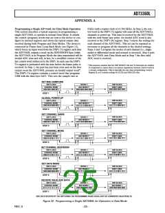
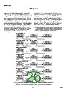
Programming a Single AD73360L for Mixed Mode Operation
This section describes a typical sequence in programming a
single AD73360L to operate in Mixed Mode. The device is
configured in Nonframe Sync Loop-Back (see Figure 11), which
allows the DSP’s Tx Register to determine how many words are
sent to the device during one sample interval. In Nonframe
Sync Loop-Back mode, care must be taken when writing to
the AD73360L that an ADC result or register read result con-
tained in the device’s serial register is not corrupted by a write.
The best way to avoid this is to only write control words when
the AD73360L has no more data to send. This can limit the
number of times a DSP can write to the AD73360L and is
dependant on the SCLK speed and the number of channels
powered up. In this example it is assumed that there are only
two channels powered up and that there is adequate time to
transmit data after the ADC results have been read.
In Step 1, the device has just been reset and the on first output
event the AD73360L presents an invalid ADC sample word*.
Once this word has been received the DSP can begin transmit-
ting programming information to the AD73360L. The first
control word sets the sampling rate at 8 kHz. In Step 2, the
DSP instructs the AD73360L to power up channels 1 and 2
and sets the gain of each. No data is read from the AD73360L
at this point. Steps 3 and 4 set the reference and places the part
into Mixed Mode. In Steps 5 and 6 valid ADC results are read
from the AD73360L and in Step 7 the DSP sends an instruc-
tion to the AD73360L to change the gain of Channel 1.
*This sequence assumes that the DSP SPORT’s Rx and Tx interrupts are enabled.
It is important to ensure there is no latency (separation) between control words in
a cascade configuration. This is especially the case when programming Control
Register B, as it contains settings for SCLK and DMCLK rates.
SET 8kHz SAMPLING
DSP Tx REG
DEVICE 1
ADC WORD 1*
0000 0000 0000 0000
DSP Rx REG
CONTROL WORD
1000 0001 0000 0011
DON'T CARE
0000 0000 0000 0000
STEP 1
POWER-UP CHANNEL 1 AND 2 AND SET GAINS
DSP Rx REG
DSP Tx REG
DEVICE 1
CONTROL WORD
ADC WORD 1*
DON'T CARE
0000 0000 0000 0000
1000 0011 1111 1010
1011 1001 0000 0011
STEP 2
POWER-UP REFERENCE
DSP Rx REG
DSP Tx REG
DEVICE 1
CONTROL WORD
ADC WORD 1*
DON'T CARE
0000 0000 0000 0000
1000 0010 1110 0000
1011 1011 1111 1010
STEP 3
SET MIXED MODE
DSP Rx REG
DSP Tx REG
DEVICE 1
CONTROL WORD
ADC WORD 1*
DON'T CARE
0000 0000 0000 0000
1000 0000 0000 0010
1011 1010 1110 0000
STEP 4
RECEIVE VALID ADC DATA
DSP Rx REG
DSP Tx REG
DEVICE 1
CONTROL WORD
ADC WORD 1
ADC WORD 1
1000 0000 0000 0000
0111 1111 1111 1111
1000 0000 0000 0000
STEP 5
RECEIVE VALID ADC DATA
DSP Rx REG
DSP Tx REG
DEVICE 1
CONTROL WORD
ADC WORD 2
ADC WORD 2
1111 0000 0000 0000
0111 1111 1111 1111
1111 0000 0000 0000
STEP 6
CHANGE GAIN ON CHANNEL 1
DSP Rx REG
DSP Tx REG
DEVICE 1
CONTROL WORD
INVALID DATA
ADC WORD 2
1111 0000 0000 0000
1000 0011 1000 0010
xxxx xxxx xxxx xxxx
STEP 7
*ADC DATA RECEIVED BY THE DSP DURING THE PROGRAMMING PHASE SHOULD NOT BE CONSIDERED VALID RESULTS.
Figure 33. Programming a Single AD73360L for Operation in Mixed Mode
–26–
REV. 0

 ADI [ ADI ]