AD73360L
APPENDIX D
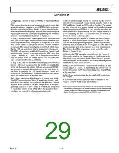
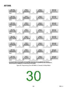
Configuring a Cascade of Two AD73360Ls to Operate in Mixed
Mode
In Step 4, another sample interval has occurred and the SDOFS
on both devices are raised. Device 2 sends an ADC result to the
DSP and Device 1 sends an ADC result to Device 2. The remain-
ing time before the next sample interval can be used to program
more registers in the AD73360Ls. Care must be taken that the
subsequent writes do not overlap the next sample interval to
avoid corrupting the data. The control words are written as
Device 2, Device 1, Device 2, etc.
This section describes a typical sequence of control words that
would be sent to a cascade of two AD73360Ls to configure
them for operation in Mixed Mode. It is not intended to be a
definitive initialization sequence, but will show users the typical
input/output events that occur in the programming and operation
phases*. This description panel refers to Figure 35.
In Step 1, we have the first output sample event following device
reset. The SDOFS signal is raised on both devices simultaneously,
which prepares the DSP Rx register to accept the ADC word
from Device 2 while SDOFS from Device 1 becomes an SDIFS
to Device 2. The cascade is configured as nonFSLB, which means
that the DSP has control over what is transmitted to the cascade.
The DSP will receive an invalid ADC word from Device 2 and
simultaneously Device 2 is receiving an invalid ADC word from
Device 1. As both AD73360Ls are in Program Mode there is
only one output event per sample period. The DSP can now
send a control word to the AD73360Ls.
Step 5 shows the DSP starting to program the ADC Control
Register to select channel gains, operating modes etc. In this
case the first write operation programs Control Register D to
power up ADC Channels 1 and 2 with gains of 0 dBs. This step
can be repeated until all the registers have been programmed.
The devices should be programmed in the order Device 2,
Device 1, Device 2, etc.
In Step 6, the DSP transmits a control word for Device 2.
This control word set the Device count to 2 and instructs the
AD73360L to go into Mixed Mode. When Device 1 receives
this control word, it will decrement the address field and generate
an SDOFS to pass it on to Device 2.
In Step 2, the DSP has finished transmitting the control word to
Device 1. Device 1 recognizes that this word is not intended for
it so it will decrement the address field and generate and SDOFS
and proceed to transmit the control word to the next device in
the chain. At this point the DSP should transmit a control word
for Device 1. This will ensure that both devices receive, and act
upon, the control words at the same time.
In Step 7, the DSP transmits a control word for Device 1. This
should happen as Device 1 is transmitting the control word for
Device 2 to ensure that both devices change into Mixed Mode
at the same time.
In Step 8, we begin receiving the first valid ADC words from
the cascade.
Step 3 shows completion of the first series of control word writes.
The DSP has now received an ADC word from Device 2 and
each device has received a control word that addresses Control
Register B and sets the SCLK and Sample Rate. When pro-
gramming a cascade of AD73360Ls in NonFSLB it is important
to ensure that control words which affect the operation of the
serial port are received by all devices simultaneously.
It is assumed that there is sufficient time to transmit all the
required Control Words in the allotted time.
*This sequence assumes that the DSP SPORT’s Rx and Tx interrupts are enabled.
It is important to ensure there is no latency (separation) between control words in
a cascade configuration. This is especially the case when programming Control
Register B, as it contains settings for SCLK and DMCLK rates.
–29–
REV. 0

 ADI [ ADI ]