Data Sheet
AD5290
THEORY OF OPERATION
PROGRAMMING THE VARIABLE RESISTOR
where:
D is the decimal equivalent of the binary code loaded in
the 8-bit RDAC register from 0 to 255.
Rheostat Operation
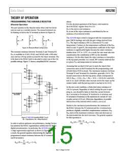
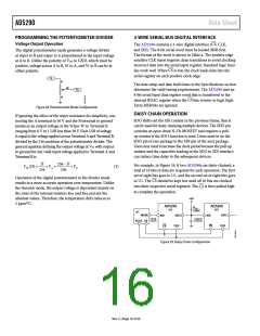
The part operates in the rheostat mode when only two termi-
nals are used as a variable resistor. The unused terminal can
be floating or tied to the W terminal as shown in Figure 26.
R
AB is the end-to-end resistance.
RW is one of the wiper resistances contributed by the on
resistance of an internal switch.
A
A
A
The AD5290 wiper switch is designed with the transmission
gate CMOS topology and with the gate voltage derived from
VDD. The wiper resistance, RW, is a function of VDD and
temperature. Contrary to the temperature coefficient of the RAB,
which is only 35 ppm/°C, the temperature coefficient of the wiper
resistance is significantly higher because the wiper resistance
doubles from 25°C to 125°C. As a result, the user must take into
consideration the contribution of RW on the desirable
W
W
W
B
B
B
Figure 26. Rheostat Mode Configuration
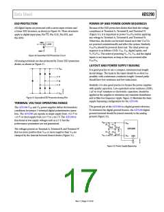
The nominal resistance between Terminal A and Terminal B,
RAB, is available in 10 kΩ, 50 kΩ, and 100 kΩ with 30% toler-
ance and has 256 tap points accessed by the wiper terminal. The
8-bit data in the RDAC latch is decoded to select one of the 256
possible settings. Figure 27 shows a simplified RDAC structure.
resistance. On the other hand, the wiper resistance is insensitive
to the tap point potential. As a result, RW remains relatively flat
at a given VDD and temperature at various codes.
A
Assuming that an ideal 10 kΩ part is used, the wiper’s first
connection starts at the B terminal for the programming code
of 0x00 where SWB is closed. The minimum resistance between
Terminal W and Terminal B is, therefore, generally 150 Ω. The
second connection is the first tap point, which corresponds to
189 Ω (RWB = 1/256 × RAB + 3RW = 39 Ω + 150 Ω) for code 0x01,
and so on. Each LSB data value increase moves the wiper up the
resistor ladder until the last tap point is reached at 10,110 Ω.
4R
4R
S
S
2R
2R
4R
S
S
S
R
W
R
R
S
In the zero-scale condition, a finite total wiper resistance of
150 Ω is present. Regardless of which setting the part is oper-
ating in, care should be taken to limit the current between
the A terminal to B terminal, W terminal to A terminal, and
W terminal to B terminal, to the maximum dc current of 5 mA
or pulse current of 20 mA. Otherwise, degradation, or possible
destruction of the internal switch contact, can occur.
W
R
W
S
8-BIT ADDRESS
DECODER
2R
2R
S
S
R
W
4R
4R
S
S
Similar to the mechanical potentiometer, the resistance of
the RDAC between the W terminal and the A terminal also
produces a digitally controlled complementary resistance, RWA.
RWA starts at the maximum resistance value and decreases as
the data loaded into the latch increases. The general equation
for this operation is
B
Figure 27. AD5290 Simplified RDAC Circuit.
(RS = Step Resistor, RW = Wiper Resistor)
256 − D
256
RWA (D) =
×RAB + 3×RW
(2)
In order to achieve optimum cost performance, Analog Devices
has patented the RDAC segmentation architecture for all the
digital potentiometers. In particular, the AD5290 employs a
3-stage segmentation approach as shown in Figure 27. As
a result, the general equation determining the digitally
programmed output resistance between the W terminal
and B terminal is
D
256
RWB (D) =
× RAB + 3× RW
(1)
Rev. C | Page 15 of 20

 ADI [ ADI ]