Data Sheet
AD5232
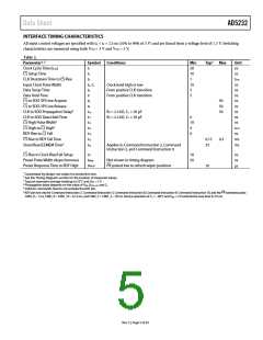
INTERFACE TIMING CHARACTERISTICS
All input control voltages are specified with tR = tF = 2.5 ns (10% to 90% of 3 V) and are timed from a voltage level of 1.5 V. Switching
characteristics are measured using both VDD = 3 V and VDD = 5 V.
Table 2.
Parameter1, 2
Symbol
t1
t2
Conditions
Min
20
10
1
Typ 3
Max
Unit
ns
Clock Cycle Time (tCYC
CS Setup Time
)
ns
CLK Shutdown Time to CS Rise
Input Clock Pulse Width
Data Setup Time
t3
tCYC
ns
ns
t4, t5
t6
t7
Clock level high or low
From positive CLK transition
From positive CLK transition
10
5
5
Data Hold Time
ns
CS to SDO-SPI Line Acquire
CS to SDO-SPI Line Release
CLK to SDO Propagation Delay4
CLK to SDO Data Hold Time
CS High Pulse Width5
t8
40
50
50
ns
t9
ns
t10
t11
t12
t13
t14
t15
t16
RP = 2.2 kΩ, CL < 20 pF
RP = 2.2 kΩ, CL < 20 pF
ns
ns
ns
0
10
4
CS High to CS High5
tCYC
ns
RDY Rise to CS Fall
0
CS Rise to RDY Fall Time
Store/Read EEMEM Time6
0.15
25
0.3
ms
ms
Applies to Command Instruction 2, Command
Instruction 3, and Command Instruction 9
CS Rise to Clock Rise/Fall Setup
Preset Pulse Width (Asynchronous)
Preset Response Time to RDY High
t17
10
50
ns
ns
µs
tPRW
tPRESP
Not shown in timing diagram
PR pulsed low to refresh wiper positions
70
1 Guaranteed by design; not subject to production test.
2 See the Timing Diagrams section for the location of measured values.
3 Typicals represent average readings at 25°C and VDD = 5 V.
4 Propagation delay depends on the value of VDD, RPULL-UP, and CL.
5 Valid for commands that do not activate the RDY pin.
6
PR
RDY pin low only for Command Instruction 2, Command Instruction 3, Command Instruction 8, Command Instruction 9, Command Instruction 10, and the hardware pulse:
CMD_8 ~ 1 ms, CMD_9 = CMD_10 ~ 0.12 ms, and CMD_2 = CMD_3 ~ 20 ms. Device operation at TA = −40°C and VDD < 3 V extends the save time to 35 ms.
Rev. C | Page 5 of 24

 ADI [ ADI ]