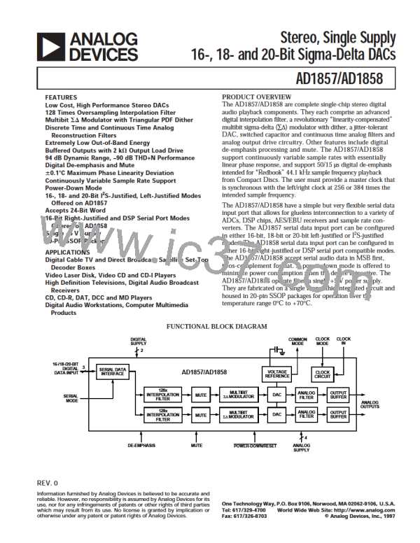
AD1857/AD1858
D IGITAL TIMING (Guar anteed over 0°C to +70°C, AVD D = D VD D = +5.0 V ± 5%)
Min
Max
Units
tDML
tDMH
tDMP
tDML
tDMH
tDMP
tDBH
tDBL
tDBP
MCLK LO Pulse Width (256 × FS Mode)
MCLK HI Pulse Width (256 × FS Mode)
MCLK Period (256 × FS Mode)
MCLK LO Pulse Width (384 × FS Mode)
MCLK HI Pulse Width (384 × FS Mode)
MCLK Period (384 × FS Mode)
BCLK HI Pulse Width
BCLK LO Pulse Width
BCLK Period
LRCLK Setup
LRCLK Hold
35
40
88.577
25
25
59.0514
20
20
354.308
20
5
5
ns
ns
ns
ns
ns
ns
ns
ns
ns
ns
ns
ns
ns
ns
tDLS
tDLH
tDDS
tDDH
tPDRP
SDAT A Setup
SDAT A Hold
PD/RST LO Pulse Width
10
4 MCLK Periods
(355 ns @ 11.2896 MHz)
P O WER
Min
Typ
Max
Units
Supplies
Voltage, Analog and Digital
Analog Current
Analog Current – Power-Down
Digital Current
Digital Current – Power-Down
Dissipation
4.75
5
5.25
40
60
25
11
V
35
30
20
5
mA
µA
mA
mA
Operation – Both Supplies
Operation – Analog Supply
Operation – Digital Supply
Power-Down – Both Supplies
Power Supply Rejection Ratio
1 kHz 300 mV p-p Signal at Analog Supply Pins
20 kHz 300 mV p-p Signal at Analog Supply Pins
275
175
100
25
325
200
125
56
mW
mW
mW
mW
–60
–50
dB
dB
TEMP ERATURE RANGE
Min
Typ
Max
Units
Specifications Guaranteed
Functionality Guaranteed
Storage
25
°C
°C
°C
0
–55
70
125
ABSO LUTE MAXIMUM RATINGS*
Min
Typ
Max
Units
DVDD to DGND
AVDD to AGND
Digital Inputs
Analog Outputs
AGND to DGND
Reference Voltage
Soldering
–0.3
–0.3
DGND – 0.3
AGND – 0.3
–0.3
6
6
V
V
V
V
V
DVDD + 0.3
AVDD + 0.3
0.3
Indefinite Short Circuit to Ground
+300
10
°C
sec
*Stresses greater than those listed under Absolute Maximum Ratings may cause permanent damage to the device. T his is a stress rating only; functional operation of the
device at these or any other conditions above those indicated in the operational section of this specification is not implied. Exposure to absolute maximum rating conditions
for extended periods may affect device reliability.
REV. 0
–3–

 ADI [ ADI ]