Actel Fusion Mixed-Signal FPGAs
Analog Quad ACM Description
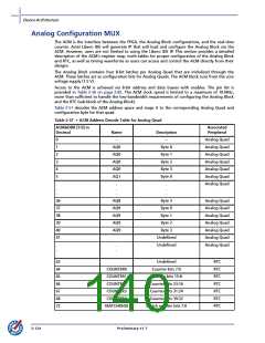
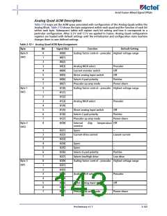
Table 2-53 maps out the ACM space associated with configuration of the Analog Quads within the
Analog Block. Table 2-53 shows the byte assignment within each quad and the function of each bit
within each byte. Subsequent tables will explain each bit setting and how it corresponds to a
particular configuration. After 3.3 V and 1.5 V are applied to Fusion, Analog Quad configuration
registers are loaded with default settings until the initialization and configuration state machine
changes them to user-defined settings.
Table 2-53 • Analog Quad ACM Byte Assignment
Byte
Bit
0
1
2
3
4
5
6
7
0
1
2
3
4
5
6
7
0
Signal (Bx)
B0[0]
B0[1]
B0[2]
B0[3]
B0[4]
B0[5]
B0[6]
B0[7]
B1[0]
B1[1]
B1[2]
B1[3]
B1[4]
B1[5]
B1[6]
B1[7]
B2[0]
Function
Default Setting
Byte 0
(AV)
Scaling factor control – prescaler Highest voltage range
Analog MUX select
Prescaler
Off
Current monitor switch
Direct analog input switch
Selects V-pad polarity
Prescaler op amp mode
Off
Positive
Power-down
Byte 1
(AC)
Scaling factor control – prescaler Highest voltage range
Analog MUX select
Prescaler
Direct analog input switch
Selects C-pad polarity
Off
Positive
Power-down
Prescaler op amp mode
Byte 2
(AG)
Internal
monitor
chip
temperature Off
1
2
3
4
5
6
7
0
1
2
3
4
5
6
7
B2[1]
B2[2]
B2[3]
B2[4]
B2[5]
B2[6]
B2[7]
B3[0]
B3[1]
B3[2]
B3[3]
B3[4]
B3[5]
B3[6]
B3[7]
Spare
–
Current drive control
Lowest current
Spare
–
Spare
–
Selects G-pad polarity
Selects low/high drive
Positive
Low drive
Byte 3
(AT)
Scaling factor control – prescaler Highest voltage range
Analog MUX select
Prescaler
Direct analog input switch
Off
–
–
Prescaler op amp mode
Power-down
Preliminary v1.7
2-127

 ACTEL [ Actel Corporation ]