BATTERY PROTECTION IC FOR 2-SERIAL TO 4-SERIAL-CELL PACK (SECONDARY PROTECTION)
S-8264A/B/C Series
Rev.4.4_00
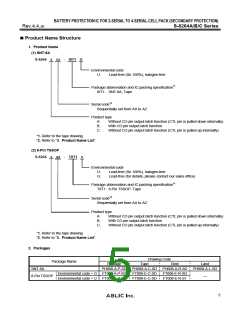
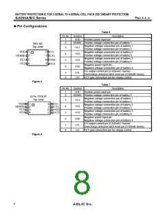
Pin Configurations
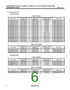
Table 6
Pin No. Symbol
Description
1
2
VDD
Positive power input pin
SENSE Positive voltage connection pin of battery 1
SNT-8A
Top view
Negative voltage connection pin of battery 1
VC1
3
4
5
6
Positive voltage connection pin of battery 2
VDD 1
8 CO
Negative voltage connection pin of battery 2
VC2
Positive voltage connection pin of battery 3
SENSE 2
7
6
5
CTL
VSS
VC3
Negative voltage connection pin of battery 3
VC3
3
VC1
Positive voltage connection pin of battery 4
4
VC2
Negative power input pin
VSS
Negative voltage connection pin of battery 4
CO output control pin (S-8264A/C Series)
CTL
7
8
Overcharge detection latch reset pin (S-8264B Series)
FET gate connection pin for charge control
CO
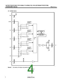
Figure 4
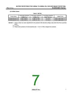
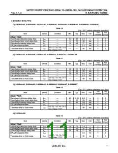
Table 7
Description
Pin No. Symbol
1
2
VDD
Positive power input pin
SENSE Positive voltage connection pin of battery 1
8-Pin TSSOP
Top view
Negative voltage connection pin of battery 1
VC1
3
4
5
6
Positive voltage connection pin of battery 2
VDD
SENSE
VC1
CO
1
8
7
6
5
Negative voltage connection pin of battery 2
VC2
CTL
VSS
VC3
2
3
4
Positive voltage connection pin of battery 3
Negative voltage connection pin of battery 3
VC3
VC2
Positive voltage connection pin of battery 4
Negative power input pin
VSS
Negative voltage connection pin of battery 4
CO output control pin (S-8264A/C Series)
CTL
7
8
Overcharge detection latch reset pin (S-8264B Series)
CO
FET gate connection pin for charge control
Figure 5
8

 ABLIC [ ABLIC ]