BATTERY PROTECTION IC FOR 2-SERIAL TO 4-SERIAL-CELL PACK (SECONDARY PROTECTION)
Rev.4.4_00
S-8264A/B/C Series
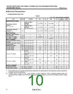
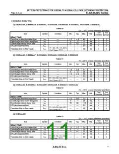
2. Detection Delay Time
(1) S-8264AAA, S-8264AAB, S-8264AAC, S-8264AAE, S-8264AAH, S-8264BAA, S-8264BAB, S-8264BAC
Table 10
(Ta = 25°C unless otherwise specified)
Test
Test
Item
Symbol
Condition
Min.
Typ.
Max.
Unit
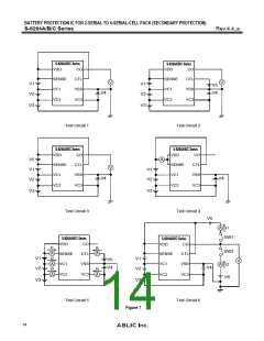
Condition Circuit
DELAY TIME
Overcharge detection delay time
Overcharge timer reset delay time
Overcharge release delay time
CTL pin response time
tCU
tTR
tCL
⎯
⎯
⎯
⎯
3.2
6
51
⎯
4.0
12
64
⎯
4.8
20
77
s
2
3
2
4
1
1
1
2
ms
ms
ms
tCTL
2.5
V1
VDD
=
V2
=
V3
+
=
V4
8.5 V
=
3.5 V,
Transition time to Test mode
tTST
⎯
⎯
80
ms
5
3
≥
VSENSE
(2) S-8264AAD, S-8264AAF, S-8264AAG, S-8264AAI, S-8264CAA, S-8264CAB
Table 11
(Ta = 25°C unless otherwise specified)
Test
Test
Item
Symbol
Condition
Min.
Typ.
Max.
Unit
Condition Circuit
DELAY TIME
Overcharge detection delay time
Overcharge timer reset delay time
Overcharge release delay time
CTL pin response time
tCU
tTR
tCL
⎯
⎯
⎯
⎯
1.6
6
1.6
⎯
2.0
12
2.0
⎯
2.4
20
3.0
2.5
s
2
3
2
4
1
1
1
2
ms
ms
ms
tCTL
V1
VDD
=
V2
=
V3
+
=
V4
8.5 V
=
3.5 V,
Transition time to Test mode
tTST
⎯
⎯
80
ms
5
3
≥
VSENSE
(3) S-8264AAJ, S-8264AAK, S-8264AAO, S-8264AAS, S-8264AAT, S-8264AAV
Table 12
(Ta = 25°C unless otherwise specified)
Test
Test
Item
Symbol
Condition
Min.
Typ.
Max.
Unit
Condition Circuit
DELAY TIME
Overcharge detection delay time
Overcharge timer reset delay time
Overcharge release delay time
CTL pin response time
tCU
tTR
tCL
⎯
⎯
⎯
⎯
4.5
8
70
⎯
5.65
17
88
6.8
28
110
2.5
s
2
3
2
4
1
1
1
2
ms
ms
ms
tCTL
⎯
V1
VDD
=
V2
=
V3
+
=
V4
8.5 V
=
3.5 V,
Transition time to Test mode
tTST
⎯
⎯
80
ms
5
3
≥
VSENSE
(4) S-8264AAW
Table 13
(Ta = 25°C unless otherwise specified)
Test
Test
Item
Symbol
Condition
Min.
Typ.
Max.
Unit
Condition Circuit
DELAY TIME
Overcharge detection delay time
Overcharge timer reset delay time
Overcharge release delay time
CTL pin response time
tCU
tTR
tCL
⎯
⎯
⎯
⎯
1.6
6
51
⎯
2.0
12
64
⎯
2.4
20
77
s
2
3
2
4
1
1
1
2
ms
ms
ms
tCTL
2.5
V1
VDD
=
V2
=
V3
=
V4
8.5 V
=
3.5 V,
Transition time to Test mode
tTST
⎯
⎯
80
ms
5
3
≥
VSENSE +
11

 ABLIC [ ABLIC ]