OX9162
OXFORD SEMICONDUCTOR LTD.
7.2.3 Zone2: Identification Registers
Bits Description
15
‘0’ = This is the last configuration WORD in for
the selected function in the Function-Header.
‘1’ = There is another WORD to follow for this
function.
The Zone2 region of EEPROM contains the program value
for Vendor ID and Subsystem Vendor ID. The format of
Device Identification configuration WORDs are described in
Table 10.
14:8 These seven bits define the byte-offset of the PCI
configuration register to be programmed. For
example the byte-offset of the Interrupt Pin
register is 0x3D. Offset values are tabulated in
section 4.2.
Bits Description
15
‘0’ = There are no more Zone2 (Identification)
bytes to program. Move to the next available
zone or end EEPROM program if no more zones
are enabled in the Header.
7:0 8-bit value of the register to be programmed
Table 12: Zone 3 data format (data)
‘1’ = There is another Zone2 (Identification) byte
to follow.
14:8 0x00 = Vendor ID bits [7:0].
0x01 = Vendor ID bits [15:8].
Table 13 shows which PCI Configuration registers are
writable from the EEPROM for each function.
0x02 = Subsystem Vendor ID [7:0].
0x03 = Subsystem Vendor ID [15:8].
0x03 to 0x7F = Reserved.
7:0 8-bit value of the register to be programmed
Offset Bits Description
0x02
0x03
0x06
0x06
0x06
0x09
0x0A
0x0B
0x2E
0x2F
0x3D
0x42
7:0 Device ID bits 7 to 0.
7:0 Device ID bits 15 to 8.
3:0 Must be ‘0000’.
Table 10: Zone 2 data format
7.2.4 Zone3: PCI Configuration Registers
4
Extended Capabilities.
7:5 Must be ‘000’.
The Zone3 region of EEPROM contains any changes
required to the PCI Configuration registers (with the
exception of Vendor ID and Subsystem Vendor ID which
are programmed in Zone2). This zone consists of a
function header WORD, and one or more configuration
WORDs for that function. The function header is described
in Table 11.
7:0 Class Code bits 7 to 0.
7:0 Class Code bits 15 to 8.
7:0 Class Code bits 23 to 16.
7:0 Subsystem ID bits 7 to 0.
7:0 Subsystem ID bits 15 to 8.
7:0 Interrupt pin.
7:0 Power Management Capabilities
bits 7 to 0.
7:0 Power Management Capabilities
bits 15 to 8.
Bits Description
0x43
15
‘0’ = End of Zone 3.
‘1’ = Define this function header.
Table 13: EEPROM-writable PCI configuration registers
14:3 Reserved. Write zeros.
2:0 Function number for the following configuration
WORD(s).
‘000’ = Function0
Other values = Reserved.
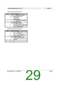
7.2.5 Zone4: Function Access
Zone 4 allows a device on the local bus (or the parallel
port) to be configured, prior to PCI access. This can be
useful for patching designs to work with generic drivers,
enabling interrupts, etc. Each 8-bit (function) access is
equivalent to accessing the function through I/O bars 0 and
1, with the exception that a function read access does not
Table 11: Zone 3 data format (Function Header)
The subsequent WORDs for each function contain the
address offset and a byte of programming data for the PCI
Configuration Space belonging to the function number
selected by the proceeding Function-Header. The format of
configuration WORDs for the PCI Configuration Registers
are described below.
return any data (discarded). Each entry in zone
4
comprises 2 16 bit words. The format is as shown in Table
14.
Data Sheet Revision 1.1 PRELIMINARY
Page 28

 OXFORD [ OXFORD SEMICONDUCTOR ]