FEDL87V2107-01
OKI Semiconductor
ML87V2107
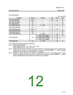
AC Characteristics
(Ta = 0 to 70°C)
Parameter
Symbol
tICLK
dtICLK
tIISU
Condition
Min.
33
40
5
Max.
—
Unit
ns
%
ICLK clock cycle time
ICLK clock duty ratio
ICLK input set-up time
ICLK input hold time
ICLK output delay time
—
—
—
60
—
ns
ns
ns
tIIH
—
3
—
tIOD
CL = 30pF
2
25
OCLK clock cycle time
tOCLK
—
33
—
ns
OCLK clock duty ratio
OCLK input set-up time
OCLK input hold time
OCLK output delay time
dtOCLK
tOISU
tOIH
—
—
40
5
60
—
—
25
20
17
20
17
20
%
ns
ns
ns
ns
—
3
tOOD
CL = 30pF
2
CL = 30 pF (IICLK output)
CL = 30 pF (ICLK output)
CL = 30 pF (OOCLK output)
CL = 30 pF (OCLK output)
CL = 30 pF
2
2
CLKO delay time
Data through time
tCKD
2
2
tDIDO
2
ns
*1: ( ) indicates the input internal system clock cycle.
Note 1: Measurement conditions
Output comparison level: VOH = VDD/2, VOL = VDD/2
Input voltage level: VIH = VDD, VIL = 0.0 V
Note 2: Writing of input data to the memory is guaranteed from the second input system vertical synchronization
signal when VDD reaches 3.0 V after the power is turned on, and when RESET = 1. (Due to memory
initialization, the first data for the first field is not guaranteed.)
Note 3: Reading of output data from the memory is guaranteed from the second output system vertical
synchronization signal when VDD reaches 3.0 V after the power is turned on, and when RESET = 1. (Due to
memory initialization, the first data for the first field is not guaranteed.)
12/152

 OKI [ OKI ELECTRONIC COMPONETS ]