Functional Description
READ WORD
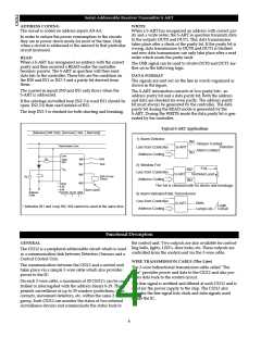
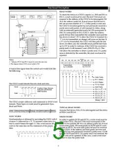
To check the status of a CS212's inputs: i.e., IN0 and IN1 or
Control
Circuit
212
212
212
3
212
29
2
IN2-3, a read word must be sent. The first 5 bits must cor-
respond to the address of the CS212 to be interrogated. Bit
#6 is the address parity bit. It must insure that the first 6
bits are an even number of "1" 's. If the parity is even and
the CS212 to be interrogated has not previously received a
parity error (odd parity), it will transmit its status, along
with an internally generated parity bit. D0 corresponds to
IN0, D1 corresponds to IN1 or IN2-3. After the address
parity bit has been transmitted the controller must pull the
line down to about 7.5V to allow the CS212 to transmit. If a
"1" is to be transmitted, no change will occur on the line. If
a "0" is to be transmitted, the CS212 will then pull the line
down. In either case, the controller must pull the line back
up to 15V in order to continue. If the CS212 has received a
parity fault, it will transmit 3 one's (D0=D1=PD=1). This
1
2 Wire
Transmission
Line
Tranmission Line
10k
V
(<14V)
CC
To Control
Bell/Det.
Etc.
1
2
3
4
5
6
7
8
16
15
14
13
12
11
10
9
DET
Loop
1mF
N0
NC
150
will allow the controller to detect a parity error. If a parity
error is detected by the controller, the read word must be
repeated.
READ D0
Notes:
A0 A1 A2 A3 A4 PA
D1 PD
BIT
1. * Indicates IN1 & loop IN2-3 cannot be used at the same time.
2. This diagram shown CS212 circuit coded to #24.
0
0
0
1
1
0
0
1
0
1
Transmitted
by CS-212
Transmitted
by Controller
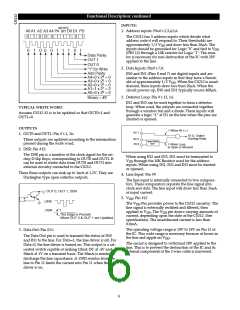
A typical line signal from the control unit would look like
the following:
0
0
0
1
1
0
0
1
0
1
Data Parity
IN 1 Status
1
0
0
1
1
IN 0 Status
"0" for Read
Add Parity
The CS212 would decode this into clock and data.
Clock
Positive Edge Strobes
A4=1 x 24 = 16
Data into an Internal
A3=1 x 23 = 8
Shift Resister
A2=0 x 22 = 0
Data
1
A1=0 x 2 = 0
0
1
0
1
1
A0=0 x 20 = 0
Binary = #24
The CS212 accepts addresses and commands in 10-bit word
formats. Three types of words must be generated: Sync,
Read and Write.
TYPICAL READ WORD
Assume that device #24 is to be interrogated and the status
of IN0=1 and IN1=0.
SYNC
READ1 READ2 READ3 READ29 SYNC WRITE1 WRITE2
WRITE29
SYNC WORD
WRITE WORD
Synchronization is obtained by providing the CS212 with 8
or more 1's followed by a "0". To prevent a false sync, it is
best to send 0 before the eight 1's. This word insures all cir-
cuits on the same line see the commands at the proper
time.
In order to update OUT0 and OUT1, a write word must be
sent to the CS212. The first 5 bits must correspond to the
CS212 to be updated. Bit #6 is an address parity bit. It must
insure even parity. D0 corresponds to OUT0 and D1 corre-
sponds to OUT1. An even data parity bit must be received
by the CS212. If the address and data parity are even and
the CS212 has not previously received a parity error, it will
update OUT0 and OUT1. If a parity error was received, the
CS212 will not be updated. In this case, a read word must
be sent to clear the parity fault.
0
1
1
1
1
1
1
1
1
0
5

 CHERRY [ CHERRY SEMICONDUCTOR CORPORATION ]