Serial-Addressable Receiver Transmitter S-ART
WRITE
ADDRESS CODING
The circuit is coded on address inputs A0-A4.
When a S-ART has recognized an address with correct par-
ity and a write order, the S-ART in question transmits data
to the outputs OUT0 and OUT1. This data transmission
takes place after a check of the parity bit. If the parity bit is
wrong, data transmission to OUT0 and OUT1 is blocked
and new data transmission can only take place after a read
order which resets the parity fault.
In order to reduce the power consumption to the circuits
they are in power down mode for most of the time. Only
when a circuit is addressed is the amount to that particular
circuit increased.
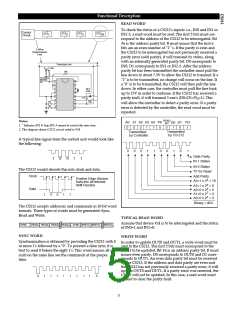
READ
When a S-ART has recognized an address with the correct
parity and then received a READ-order the controller
becomes passive. The S-ART in question will then send
data bits to the controller. These bits are the condition on
the IN0 and IN1 or IN2-3 and a parity bit derived from
them.
The DSR signal can be used to strobe OUT0 and OUT1 fur-
ther on in the following logic.
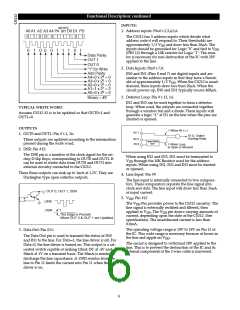
DATA FORMAT
The signals are sent out on the line in words organized as
shown in the figure.
The current in inputs IN0 and IN1 only flows when the
S-ART is addressed.
The S-ART information consists of two parity bits: an
address parity bit and a data parity bit. Both the address
and data are checked for even parity. The address parity
bit must always be generated by the controller. The data
parity bit during the READ-mode is generated by the
S-ART. During the WRITE-mode the data parity bit is gen-
erated by the controller.
If the sabotage surveilled loop IN2-3 is used IN1 should be
open. IN2-3 is then read instead of IN1.
The loop IN2-3 is checked for both shorting and breaking.
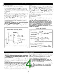
Typical S-ART Applications
Addresses ADD. Parity Command Data Data Parity
1) Alarm Detector
IN0
Tamper Contact
Transmission Line
Line
Detector
Line from Controller
Address Coding
S-ART
Alarm Contact
IN1
Gnd
Gnd
IN0
R1
Data
Out
+IN1
2) Window Foil
Foil
VDD
IN2
Line from Controller
Address Coding
+IN2
+IN3
S-ART
Terminal Lead
C
End of Loop
Circuit
R2
IN3
Gnd
A0
A4
The foil is checked both for shorts and breakage.
Short Cables
OUT0 OUT1 DSR
Address
Code
3) Alarm Indicator/Data Transmission
Line from Controller
Address Coding
Bells
Lamps etc. Circuit
S-ART
Logic
+ Indicates IN1 and Loop IN2, IN3 cannot be used at the same time.
Functional Description
GENERAL
the control unit. Two outputs are also available for control-
ling bells, lights, LED's, door locks, etc. These outputs are
controlled from the control unit via the 2-wire cable.
The CS212 is a peripheral addressable circuit which is used
as a communication link between Detectors/Sensors and a
Central Control Unit.
WIRE TRANSMISSION CABLE (The Line)
The communication between the CS212 and a control unit
takes place via a simple 2-wire cable which also provides
power to the IC.
The 2-wire bidirectional transmission cable called "The
Line" provides power and data to the CS212 and also pro-
vides data back to the control circuit.
On each 2-wire cable, a maximum of 30 CS212's can be con-
trolled or interrogated with the address binary 0-29. This
permits surveillance of up to 30 window protections, door
contacts, movement detectors, etc. within the same 2-wire
group. Each CS212 can monitor the status of two external
surveillance devices and communicate the status back to
The line signal is rectified and filtered at each CS212 and is
used for the power supply to the chip. The CS212 also
decodes the line signal into clock and data signals used
inside the IC.
4

 CHERRY [ CHERRY SEMICONDUCTOR CORPORATION ]