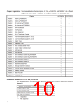
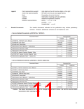
Chapter Organization: This manual divides the descriptions for the µPD78070A and 78070AY into different
chapters as shown below. Read only the chapters related to the device you use.
Chapter
µPD78070A µPD78070AY
Chapter 1
Chapter 2
Chapter 3
Chapter 4
Chapter 5
Chapter 6
Chapter 7
Chapter 8
Chapter 9
Outline (µPD78070A)
Outline (µPD78070AY)
Pin Function (µPD78070A)
Pin Function (µPD78070AY)
CPU Architecture
√
—
√
—
√
—
√
√
√
√
√
√
√
√
√
√
√
√
√
—
√
√
√
√
√
√
√
√
√
—
√
Port Functions
√
Clock Generator
√
16-bit Timer/Event Counter
√
8-bit Timer/Event Counters 1 and 2
√
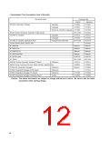
Chapter 10 8-bit Timer/Event Counters 5 and 6
Chapter 11 Watch Timer
√
√
Chapter 12 Watchdog Timer
√
Chapter 13 Clock Output Control Circuit
Chapter 14 Buzzer Output Control Circuit
Chapter 15 A/D Converter
√
√
√
Chapter 16 D/A Converter
√
Chapter 17 Serial Interface Channel 0 (µPD78070A)
Chapter 18 Serial Interface Channel 0 (µPD78070AY)
Chapter 19 Serial Interface Channel 1
Chapter 20 Serial Interface Channel 2
Chapter 21 Real-time Output Port
Chapter 22 Interrupt and Test Functions
Chapter 23 External Device Expansion Function
Chapter 24 Standby Function
√
—
√
√
√
√
√
√
Chapter 25 Reset Function
√
Chapter 26 Instruction Set
√
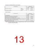
Differences between µPD78070A and µPD78070AY
The µPD78070A and µPD78070AY are different in the following functions of the serial interface
channel 0.
Mode of Serial Interface Channel 0
3-wire serial I/O mode
µPD78070A µPD78070AY
√
√
√
√
2-wire serial I/O mode
SBI (serial bus interface) mode
I2C (Inter IC) bus mode
√
—
√
—
√
: Supported
— : Not supported
10

 ETC [ ETC ]