TEA1716T
NXP Semiconductors
Resonant power supply control IC with PFC
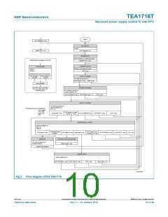
START
UVP supplies = yes
enable PFC = no
NO SUPPLY
-All off
UVP supplies = no
DISABLED lC
-Only "Enable lC" detection active
Enable PFC = yes
Explanation flow diagram symbols
STATE NAME
THERMAL HOLD
-Minimum functionality active
OTP = no
-action 1
-action 2
-...
Disabled items are not mentioned
exit condition 1 exit condition 2
SUPIC CHARGE
reached
reached
-HV start-up source on
UVP SUPIC = no
OTP = yes
exit condition
next state can be entered
from any state when exit
condition is true
SUPREG CHARGE
-HV start-up source on
-Series stabilizer on
UVP SUPREG = no
UVP SUPIC= yes
BOOST CHARGE
OTP = yes
-HV start-up source on
-Series stabilizer on
-PFC on
1
*
Protection timer is activated by:
-UVP output
-OLP HBC
-OCR HBC
-HFP
UVP boost = no and
Enable lC = yes
SCP boost = yes
UVP SUPREG = yes
UVP SUPIC = yes
OTP = yes
OPERATIONAL SUPPLY
-Series stabilizer on
-PFC on
-HBC on
Protection timer
passed *
UVP boost = yes
or Enable IC = no
SCP boost = yes
OVP output = yes Burst stop = yes
UVP SUPREG = yes
UVP SUPIC = yes OTP = yes
1
RESTART
PROTECTION SHUTDOWN
Mains reset = yes
-HV start-up source on
-Restart timer on
Restart time passed
BURST STOP
-Series stabilizer on
UVP SUPREG = yes UVP SUPIC = yes
OTP = yes
Burst stop = no
aaa-000766
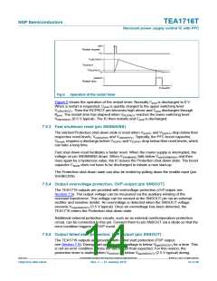
Fig 3. Flow diagram of the TEA1716
TEA1716T
All information provided in this document is subject to legal disclaimers.
© NXP B.V. 2012. All rights reserved.
Objective data sheet
Rev. 1 — 27 January 2012
10 of 46

 ETC [ ETC ]