Ver 1.3
PRELIMINARY
EAGLE
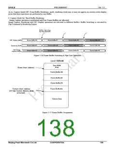
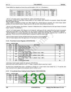
Frame Buffer Size depends on Screen Size used for display ( CRT’s X / Y Resolution ).
X Resolution Y Resolution
Buffer Size
512KB
1MB
0*0
< Display Area < 512 * 512
0
1
0
1
0
0
1
1
512 * 512 < Display Area < 1024 * 512
512 * 512 < Display Area < 512 * 1024
512 * 512 < Display Area < 1024 * 1024
1MB
2MB
The bit 1 of Control register, Engine Enable bit, enables and disables the Engine.
All parameter should be set-up before setting Enable bit. Once enabled, there should be no parameter changes that might
affect the Engine operation.
Image Capture is performed in Frame unit. When Enable bit is cleared during an operation, the current image capture
operation on screen should continue, Engine transits to Idle state after current frame execution ends.
The bit 2 of Control register, Non-Interlace / Interlace Configuration bit is configured based on the input format of external
Image ( Interlace / Non-Interlace ).
The bit 3 of Control register, FIFO Request Level Setting bit, shall request for the control of local bus based on parameter
settings and current FIFO Level. FIFO depth is 64, and 16 request configuration (Quarter Full) / 32 (Half Full) is supported.
This bit should be set to quarter full request for Multi Master System where fast data acquisition time is needed for an
application. This bit can be set to half full request to maximize overall bus request time.
Bit 8 of Control register activates and deactivates the Color Space Conversion Block.
Bit 9 of Control register selects the input source of Color Space Conversion Block.
3.14.6 Pixel Gain Control Register (CSCICPGCON)
Address : 0xFFE0 4804
Bit
31:24
23:16
15:8
7
R/W
R/W
R/W
R/W
R
Description
Default Value
Red Pixel Gain Value
Green Pixel Gain Value
Blue Pixel Gain Value
Reserved
FFh
FFh
FFh
-
6
R/W
Red Pixel Gain Control
0b
( 1: 0 dB<=Gain < 3dB, 0: -infinite< Gain < 0dB )
5
4
R/W
R/W
Green Pixel Gain Control
( 1: 0 dB<=Gain < 3dB, 0: -infinite< Gain < 0dB )
Blue Pixel Gain Control
0b
0b
( 1: 0 dB<=Gain < 3dB, 0: -infinite< Gain < 0dB )
3:1
0
R
R/W
Reserved
Gain Control Enable
-
0b
Pixel Gain Control register controls the input gain of R/G/B Data.
When Pixel Gain Control Enable bit is set to ‘0’, image is captured without using Gain Control.
The final Gain Controlled Pixel value is calculated as [ Pixel[7:0] * { Gain Control, Gain Value[7:0] } ] / 2^8 and the color
value concerned can be clipped to the maximum value if overflow occurs
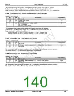
3.14.7 X Coordinate Down Scaling Control Register (CSCICXDSCON)
Address : 0xFFE0 4808
Bit
31:13
12:8
7:1
R/W
R
R/W
R
Description
Default Value
Reserved
Down Scale Factor
Reserved
-
1Fh
-
0
R/W
X Coordinate Down Scaling Enable
0: 1:1 Mapping
0b
1: Down Scaling Enable.
139
CONFIDENTIAL
Beijing Peak Microtech Co.Ltd.

 ETC [ ETC ]