Ver 1.3
PRELIMINARY
EAGLE
3.14.4 Operational Descriptions
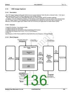
Image Capturer consists mainly of AHB Interface Module, Engine Core, Engine DMAC & FIFO Controller and 64x32
Dual Port FIFO.
1) AHB Interface Module :
The Bus Interface module for upper layer AMBA, and includes Register Bank.
The Registers are used as signal controls for Engine operation and to report current module state of Master Device.
2) CSC Image Capturer Core:
The Engine consists mainly of Main Control FSM, Pixel Gain Controller and X/Y Down Scaler.
Main Control FSM receives signals related to external image, such as Sync, Display, etc.. and controls the entire Engine
operation. The Pixel Gain Controller controls the input gain of RGB Data.
X/Y Down Scaler is used for image scaling based on Down Scale Factor.
Interrupt is request on every rising edge of Frame Sync for the convenience of Graphic related applications.
3) Engine DMAC & FIFO Controller:
Engine DMA Controller executes the bus request based on Bus Request FIFO Level configuration as well as the FIFO
Level. To acquire the authority control of bus, it communicates with Memory Controller to determine the Request Level.
FIFO Controller controls a Dual Port Sync FIFO of size 64 x 32.
3.14.5 Engine Control Register (CSCICCON)
Address : 0xFFE0 4800
Bit
31 : 10
9
R/W
R
R/W
Description
Default Value
Reserved.
-
Color-Space-Conversion Source Select
0: External Video Decoder
1: Scaler
0b
8
7 : 4
3
R/W
R
R/W
Color-Space-Conversion Block Enable.
Reserved
FIFO Request Level Setting Bits.
0: Level 32 Request
1: Level 16 Request
Non Interlace / Interlace Setting Bit.
0: Interlace Mode
0b
-
0b
0b
2
R/W
1: Non-Interlace Mode
1
0
R/W
R/W
Engine Enable
Image Capture Mode
0b
0b
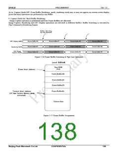
Image Capture Mode bit in Control register works with the Render to Front Buffer / Back Buffer configure Bit in Rendering
Engine to allocate the number of Frame Buffer in Memory Map.
1. Capture Mode Off / Front Buffer Rendering
Capture operation is not performed and one Frame Buffer is allocated.
In this case, Frame Buffer = Rendering Buffer = CRT Display Buffer.
Since CRT Display and Rendering shares the same Buffer, the Rendering result may or may not appear on the current screen
display, depending on the operation sequence.
2. Capture Mode Off / Back Buffer Rendering
Capture operation is not performed and two Frame Buffers are allocated.
CRT Display is processed in Front Buffer and Rendering is performed in Back Buffer.
Buffer Switching is executed by Flip Command in Rendering Engine.
Compared to the previous behavior mode, Rendering result shall be displayed on the current screen irrespective of the
Rendering operation on screen after Flip Command is performed, as separate Rendering buffer and Display buffer are used.
(Rendering Buffer = ~Display Buffer).
3. Capture Mode On / Front Buffer Rendering
Image Capture is performed and one Frame Buffer is allocated.
In this case, Frame Buffer = Image Capture Buffer = Rendering Buffer = CRT Display Buffer.
137
CONFIDENTIAL
Beijing Peak Microtech Co.Ltd.

 ETC [ ETC ]