Ver 1.3
Video Encoder Master/Slave mode control
PRELIMINARY
EAGLE
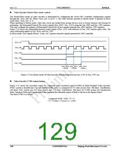
The Master/Slave mode of video encoder is determined by configuring the 18-bit CRT controller configuration register
through the “Sync_Sel” bit. When “Sync_Sel” is set to ‘1’, the video encoder operates in Master mode. It operates in Slave
mode when “Sync_Sel” is ‘0’.
When operating in Master mode, video data can be pre-loaded from storage devices such as Frame Memory and Storage by
generating the Horizontal/Vertical Pre-Active signals (Enc_HAV, Enc_VAV) using the Enc_HPC and Enc_VPC registers.
User may configure the polarity of Horizontal/Vertical Pre-Active signals using the Enc_HPC and Enc_VPC registers.
Figure 3-24 shows the relationship between output signal of Enc_VAV with reference to Enc_VPC register input value. The
same relationship applies to Env_HAV and Enc_VPC.
In Slave mode, Sync signals (Hsync, Vsync, etc.) operate using the signals generated by CRT controller.
Enc_VS
Enc_HS
Enc_VAV
Enc_VAV
Enc_VAV
Enc_VPC Enc_VPC Enc_VPC
= 8'h3F = 8'h40
= 8'h41
Figure 3-22 In Master mode of Video Encoder, Relationship between Enc_VAV & Enc_VPC reg.
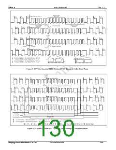
Video Encoder CVBS output timing
Figure 3-25 shows the waveform output for composite video baseband signal (CVBS) of Multi-Standard Video Encoder.
NTSC system is divided into Top and Bottom Fields and it is composed of 525 lines (Active line: 480 lines, Top/Bottom:
240 lines). PAL system uses 625 lines (Active line: 576 lines, Top/Bottom: 288 lines). In CVBS system, the Equalization
Pulse, Serration Pulse and Equalization Pulse constitute the alteration region of field as shown in the figures below.
The final CVBS is as follow.
Composite NTSC / PAL = Y + C
= Y + Usinωt + Vcosωt, ω = 2πFsc
129
CONFIDENTIAL
Beijing Peak Microtech Co.Ltd.

 ETC [ ETC ]