AND8327/D
Stability Analysis in
Multiple Loop Systems
Prepared by Christophe Basso, Stéphanie Conseil, Nicolas Cyr
http://onsemi.com
Loop stability analysis usually starts from an open-loop
Bode plot of the plant under study, e.g. the power stage of a
buck or a flyback converter. From this diagram, the designer
can extract phase and gain data within the frequency range
of interest. His job then consists in identifying a
compensator structure which will lead to the selected
crossover frequency affected by the right phase margin. The
final step requires the study of the total loop gain, the power
plant followed by the compensator, showing that the
poles/zeros placed on the compensator ensure stability once
the loop is closed. If this operation is rather straightforward
with single loops, the operation becomes more complicated
with converters implementing weighted feedback. This
paper capitalizes on the Ref. [1] work and explores different
ways to apply the technique to power converters featuring
multiple feedback paths.
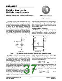
The TL431, a Multiple Loop System
The TL431 alone, can be modeled as a multiple loop
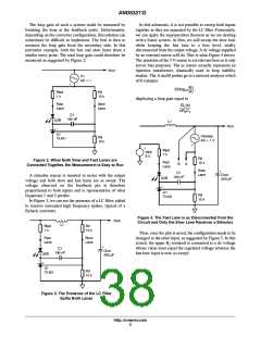
feedback system. Figure 1 shows a TL431 classically wired
in a type-2 configuration, as described in Ref. [2]. From this
schematic, one can identify so-called slow and fast lanes.
Vout
Vdd
Rled
1 k
R2
10 k
Rpullup
20 k
Fast
Lane
Slow
Lane
FB
C1
100 nF
U2B
U2A
C2
1 nF
U1
TL431
R3
10 k
Primary Side
Secondary Side
Figure 1. A TL431 Wired in a Classical Configuration, Observing the dc Voltage of a Converter
The TL431 can be seen as a programmable zener also
called a shunt regulator. When the output voltage changes,
e.g. because of a load variation, the information is conveyed
voltage. Therefore, even if you increase C , it has no effect
1
in rolling off the loop gain since R always senses the
led
output voltage. The transfer function of such a system can be
written in the following form [2]:
to the inverting input of the TL431 via R /R and asks the
3
2
programmable zener to pump more or less current into the
optocoupler LED. It does so by adjusting its cathode
voltage. By this way, the feedback signal observed on the
primary side also changes and instructs the controller to alter
its operating point. If the output voltage variations are too
VFB(s)
1
ǒ Ǔ
+ G1(s) 1 )
(eq. 1)
Vout(s)
sR2C1
where G (s) represents the mid-band gain brought by the
1
optocoupler CTR, the LED and the pull-up resistors
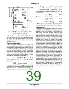
fast, the frequency sensed by R exceeds the pole position
2
introduced by C and the ac contribution of this path to the
feedback signal becomes null: the TL431 no longer changes
its operating point and the LED cathode is now fixed.
However, as the LED cathode is fixed, the anode still senses
associated to the capacitor C . From this expression, we can
2
1
actually see the presence of two loops by developing
Equationꢀ1:
VFB(s)
Vout(s)
G1(s)
+ G1(s) )
(eq. 2)
sR2C1
an output voltage variation via R . This current variation
led
propagates via the optocoupler and affects the feedback
©ꢀ Semiconductor Components Industries, LLC, 2008
April, 2008 - Rev. 0
1
Publication Order Number:
AND8327/D

 ETC [ ETC ]