10
Package Characteristics
Unless otherwise noted, all specifications are at T = +25°C.
A
Parameter
Input-Output Momentary
Withstand Voltage
Symbol Min. Typ. Max. Units
Test Conditions
RH ≤ 50%, t = 1 min.
Note
14,15
V
3750
V
rms
ISO
(See note ** below)
Resistance (Input - Output)
12
13
R
10
10
10
Ω
V
I-O
= 500 Vdc
15
I-O
11
T = 100°C
A
Capacitance
C
I-O
0.7
pF
f = 1 MHz
(Input - Output)
Input IC Junction-to-Case
Thermal Resistance
Output IC Junction-to-Case
Thermal Resistance
θ
96
°C/W Thermocouple located at
jci
center underside of
package
θ
114
°C/W
jco
** The Input-Output Momentary Withstand Voltage is a dielectric voltage rating that should not be interpreted as an input-output
continuous voltage rating. For the continuous voltage rating refer to your equipment level safety specification or Agilent Application
Note 1074, Optocoupler Input-Output Endurance Voltage.
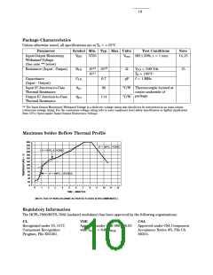
Maximum Solder Reflow Thermal Profile
260
240
∆T = 145°C, 1°C/SEC
220
∆T = 115°C, 0.3°C/SEC
200
180
160
140
120
100
80
∆T = 100°C, 1.5°C/SEC
60
40
20
0
0
1
2
3
4
5
6
7
8
9
10
11
12
TIME – MINUTES
(NOTE: USE OF NON-CHLORINE ACTIVATED FLUXES IS RECOMMENDED.)
Regulatory Information
The HCPL-7860/HCPL-786J (isolated modulator) has been approved by the following organizations:
UL
VDE
CSA
Recognized under UL 1577,
Component Recognition
Program, File E55361.
Approved under VDE 0884/06.92
Approved under CSA Component
Acceptance Notice #5, File CA
88324.
with VIORM = 848 VPEAK
.

 ETC [ ETC ]