ICs for TV
AN5195K-C
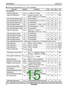
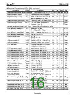
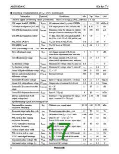
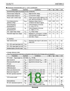
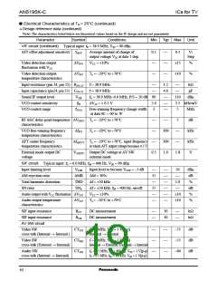
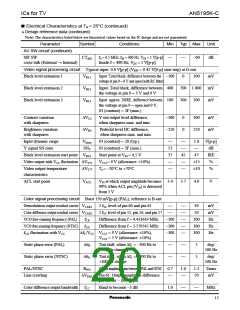
■ Electrical Characteristics at Ta = 25°C (continued)
Parameter
Symbol
Conditions
Min
Typ Max
Unit
Video signal processing circuit (continued) Typical input: 0.6 V[p-p] (VWB = 0.42 V[p-p] stair-step), at G-out
Pedestal difference voltage
Brightness voltage tracking
∆VIPL
∆TBL
Difference voltage of R,G,B-out pedestal − 0.2
0
0.2
1.1
V
R,G,B-out fluctuation level ratio of
0.9
1.0
Times
data 02 (brightness) = 20 to 60
Video voltage gain relative ratio ∆GYC
Video voltage gain tracking ∆TCONT Gain ratio of R,G,B-out at data 03
(contrast) = 10 to 30
Chroma signal processing circuit Burst 150 mV[p-p] (PAL), reference is B-out
Output ratio of R,B-out against G-out 0.8
1.0
1.0
1.2
Times
0.9
1.1 Times/
Times
Color-difference output (typ.)
VCO
Input: Color bar data
00 = 20 (typ.), 03 = 20 (typ.)
2.9
3.7
3.3
4.5 V[p-p]
Color-difference output (max.) VCOmax Data 00 = 3F, amplitude of one side, 03 = 20 2.6
Color-difference output (min.) VCOmin Data 00 = 00, 03 = 20
V[0-p]
100 mV[p-p]
Contrast variable range
CCmax/min 03 = 3F
03 = 00
15
20
25
dB
, 00 = 20
ACC characteristics 1
ACC characteristics 2
NTSC tint center
ACC1
ACC2
∆θC
Burst 150 mV[p-p] → 300 mV[p-p]
Burst 150 mV[p-p] → 30 mV[p-p]
0.9
0.8
−7
1.0
1.0
0
1.2
1.2
7
Times
Times
Step
Difference from data 01 = 20 (tint),
when adjusted at tint center
NTSC tint variable range 1
NTSC tint variable range 2
Color-difference output ratio (R)
Color-difference output ratio (G)
Color-difference output angle (R)
Color-difference output angle (G)
PAL color killer tolerance
NTSC color killer tolerance
APC pull-in range (H)
∆θ1
∆θ2
R/B
G/B
R
Input: Rainbow, data 01 = 3F
Input: Rainbow, data 01 = 00
30
50
65
deg
deg
−65
−50
−30
Input: Rainbow for both PAL/NTSC 0.46 0.56 0.66 Times
Input: Rainbow for both PAL/NTSC 0.28 0.34 0.40 Times
Input: Rainbow for both PAL/NTSC
78
90
102
248
−34
−34
deg
deg
dB
dB
Hz
Hz
V
G
Input: Rainbow for both PAL/NTSC 224
236
−44
−44
700
VKILLP 0 dB = 150 mV[p-p]
VKILLN 0 dB = 150 mV[p-p]
−57
−57
450
fCPH
fCPL
VKC
For both PAL/NTSC
For both PAL/NTSC
APC pull-in range (L)
−700 −450
Color killer detection
output voltage (color)
V5, when chroma input
Data 0A−D6 = 0, 0A−D7 = 1, killer out
4.5
0
5.0
Color killer detection
output voltage (B&W)
VKBW
VDB
V5, when chroma input
Data 0A−D6 = 0, 0A−D7 = 1, killer out
0.1
695
540
0.5
V
Demodulation output −(B−Y)
Input: Measurement at pin 60
for both color bar PAL/NTSC
555
430
835 mV[p-p]
650 mV[p-p]
Demodulation output −(R−Y)
VDR
Input: Measurement at pin 61
for both color bar PAL/NTSC
Demodulation output angle (B−Y)
Demodulation output angle (R−Y)
CW output level (4.43 MHz)
RDB
RDR
Phase shift of B−Y axis
−6
0
6
deg
deg
Phase difference from B−Y axis
84
90
96
VCWP
AC component, when VCO is set at 4.43 MHz 250
350
450 mV[p-p]
7

 ETC [ ETC ]