AN5195K-C
ICs for TV
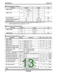
■ Absolute Maximum Ratings
Parameter
Symbol
VCC1(14)
Rating
10.5
Unit
Supply voltage
VCC
V
VCC3(23, 47)
6.0
Supply current
ICC
I14
I23+47
I51
67
mA
126
27
2
Power dissipation*
PD
1,480
mW
°C
1
Operating ambient temperature*
Topr
Tstg
−20 to + 70
−55 to + 150
1
Storage temperature *
°C
Note) 1 : Except fot the operating ambient temperature and storage temperature, all ratings are for T = 25°C.
*
a
2 : The power dissipation shown is the value for T = 70°C.
*
a
■ Recommended Operating Range
Parameter
Supply voltage
Symbol
Range
8.1 to 9.9
4.5 to 5.5
10 to 25
Unit
VCC1
VCC3
I51
V
Supply current
mA
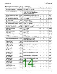
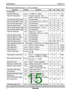
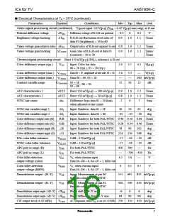
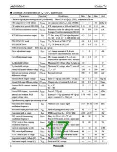
■ Electrical Characteristics at Ta = 25°C
Parameter
Power supply
Symbol
Conditions
Min
Typ Max
Unit
Supply current 1
I14
I23
Current at V14 = 9 V
39
7
48
10
63
6.5
5
57
13
77
7.2
7
mA
mA
mA
V
Supply current 2
Current at V23 = 5 V
Current at V47 = 5 V
Voltage at I51 = 15 mA
Current at V51 = 5 V
Supply current 3
I47
49
5.8
2
Stabilized power supply voltage
Stabilized power supply current
V51
I51
mA
Ω
Stabilized power supply
input resistance
R51
DC measurement, gradient
at I51 = 10 mA and 25 mA
1
5
10
VIF circuit Typical input: fP = 38.9 MHz, VIN = 90 dBµ
Video detection output (typ.)
Video detection output (max.)
Video detection output (min.)
Video detection output f characteristics
Sync. peak value voltage
VPO
Modulation m = 87.5%, data 0B = 44 1.7
2.1
2.6
1.6
8
2.5 V[p-p]
3.3 V[p-p]
2.1 V[p-p]
VPOmax 0B = 74
VPOmin 0B = 04
1.9
1.1
5.5
1.6
1.0
fPC
VSP
fPPH
Frequency to become −3 dB for 1 MHz
12
MHz
V
Sync. peak voltage at V[p-0] measurement
2.0
2.0
2.4
APC pull-in range (H)
High band side pull-in range
MHz
(difference from fP = 38.9 MHz)
APC pull-in range (L)
fPPL
Low band side pull-in range
−2.0 −1.0
MHz
(difference from fP = 38.9 MHz)
RF AGC delay point adjusting ∆VRFDP Delay point (input to become
range V27 = approx. 6.5 V) at data 0A = 00 to 3F
75
95
dBµ
4

 ETC [ ETC ]