SYNTHESIZED REFERENCE
BUILT-IN-TEST (BIT)
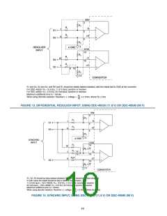
The synthesized reference section of the RD-19.30 eliminates
errors due to phase shift between the reference and signal
inputsꢀ Quadrature voltages in a resolver or synchro are by def-
inition the resulting 90° fundamental signal in the nulled out error
voltage (e) in the converterꢀ Due to the inductive nature of syn-
chros and resolvers, their output signals lead the reference input
signal (RH and RL)ꢀ When an uncompensated reference signal
is used to demodulate the control transformer’s output, quadra-
ture voltages are not completely eliminatedꢀ As shown in FIG-
URE 1, the converter synthesizes its own internal reference sig-
nal based on the SIN and COS signal inputsꢀ Therefore, the
phase of the synthesized (internal) reference is determined by
the signal input, resulting in reduced quadrature errorsꢀ
The BIT output is active low, and will be asserted during the fol-
lowing three error conditions:
Loss of Signal (LOS) - Sin and Cos inputs both less than 500mVꢀ
Loss of Reference (LOR) - Reference Input less than 500 mVꢀ
Excessive Error - This error is detected by monitoring the
demodulator output, which is proportional to the difference
between the analog input and digital outputꢀ When it exceeds
approximately 100 LSBs (in the selected resolution), BIT will be
assertedꢀ This condition can occur any time the analog input
changes at a rate in excess of the maximum tracking rateꢀ
During power up, the converter may see a large difference
between the sin/cos inputs and the digital output angle held in its
counterꢀ BIT will be asserted until the converter settles within
~ 100 LSB’s of the final resultꢀ
RD-19.30
1 MSB
.
3
4
5
6
7
8
9
10
11
1.
13
14
15
BIT 16 LSB
1
0
1
.
1
4
1
6
A
B
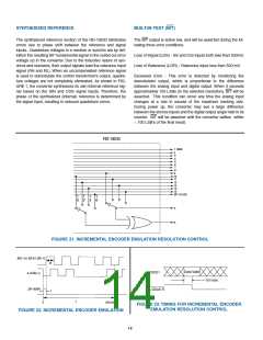
FIGURE 21. INCREMENTAL ENCODER EMULATION RESOLUTION CONTROL
B(X- or LSB & LSB+1)
A (LSB+1)
.t
Data Valid
D0/D1
50 nsec
ZIP (NRP)
A QUAD B
t
T
359ꢀ95
0
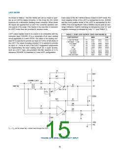
FIGURE 23. TIMING FOR INCREMENTAL ENCODER
EMULATION RESOLUTION CONTROL
FIGURE 22. INCREMENTAL ENCODER EMULATION
14

 ETC [ ETC ]