Pro-Wave Electronics Corp.
Tel: 886-2-22465101
Fax: 886-2-22465105
E-mail: sales@pro-wave.com.tw
URL: http://www.prowave.com.tw
The resonate frequency of ultrasonic piezo transducers varies in an inversely proportional relationship to
temperature. The lower the temperature, the higher the resonate frequency, the higher the temperature the lower
the resonate frequency.
This property of piezo transducers may cause a mismatch between transducer and drive signal with changes in
ambient temperature and reduces efficiency of the system when the frequency of the drive circuit remains constant
and does not track the resonate frequency shift of the transducer.
Therefore it is desirable to have the output frequency of the drive source track the resonate frequency of the
transducer with changes in ambient temperature. The Auto Frequency Tracking circuitry between Ftrace, (pin 12),
and Drive_O, (pin 11) is used to accomplish this task.
The voltage change at Ftrace (pin 11) varies in proportion to the forward bias voltage change across diodes D1, D2.
This change is caused by the negative temperature coefficient of the diodes and the ratio of the resistor circuit
R2/R3.
A lower temperature increases the voltage drop across the diodes. This intern accelerates the charge rate of an
internal integrator circuit controlling the R/C Oscillator, ORC3, (pin15). The net result is the adjustment to the
R/C Oscillator increases the resonate frequency of the output, Drive_O, (pin11).
Conversely, a higher temperature decreases the voltage drop across the diodes. This slows the charge rate of the
internal integrator circuit controlling the R/C Oscillator. The net result of this adjustment is to decrease the resonate
frequency of the output Drive_O, (pin 11).
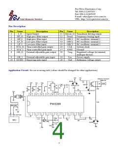
Choose values for the components R1, R2, R3 and C1 that will best track the characteristic resonate frequency shift
curves due to temperature for a specific transducer.
Recommended values for the following transducers are listed below.
Used Transducer
400EP14D
R1(Ohm)
3,300
R2(Ohm)
1,500
1,500
0
R3(Ohm)
511
C1(pF)
2,200
2,200
220
400EP18A
235AC130
3,300
2,000
604
2,100
For a fixed output of 40KHz at Drive_O (pin 11) simply remove D1, D2 and R2 and set R1 = 4,500 Ohm, C1 =
2,200 pF, and R3 = 511 Ohm.
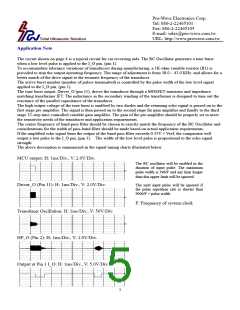
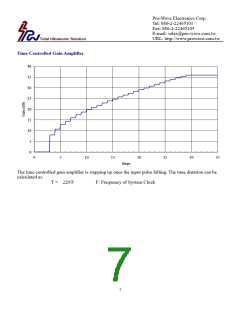
The system clock CLK (pin 16) controls the maximum input pulse width, the slope of time controlled gain
amplifier and pulse repetition rate.
For example, as illustrated in the block diagram, if the system clock is set to 660KHz (C2: 22pF, R4: 47K Ohm),
then:
(1) The maximum input pulse width is 396/F = 396/660K = 0.6 ms and any duration longer than 0.6ms will be
ignored.
(2) The step duration of the 32 step time controlled gain amplifier is equal to 220/F = 0.333 ms, starting from
the end of the pulse on the I_O pin, (pin 1).
(3) The minimum pulse repetition rate is 9900/F + pulse width = 9900/F + 0.5 ms (20 bursts of 40KHz) =
9900/660K + 0.5 = 15.5 ms.
For long distance measurements of 18 meters (one way distance), the system clock should be set as follows:
Min. Pulse Repetition Rate = 9900/F + 0.75 = 166 mS (30 bursts of 40KHz)
Frequency of System Clock F = 60 KHz
For additional information about an 18-meter tape measure circuit, please consult with the factory.
6

 ETC [ ETC ]