Pro-Wave Electronics Corp.
Tel: 886-2-22465101
Fax: 886-2-22465105
E-mail: sales@pro-wave.com.tw
URL: http://www.prowave.com.tw
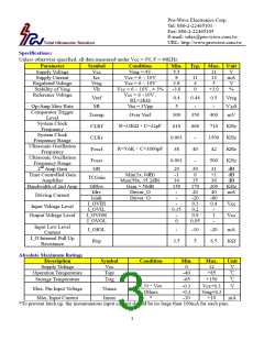
Specifications:
Unless otherwise specified, all data measured under Vcc = 9V, F = 40KHz
Parameter
Symbol
Vcc
Icc
Vreg
Vlr
Condition
Vreg = 4V
Min.
5.5
8
3.8
-3.0
Typ. Max. Unit
Supply Voltage
Supply Current
Regulated Voltage
Stability of Vreg
Reference Voltage
11
14
5
V
mA
V
Vcc = 6 ~ 10V
Vcc = 6 ~ 10V
Vcc = 6 ~ 10V , ± 3%
Vcc = 6 ~10V ,
RL>2KΩ
11
4
0
+3.0
%
Vref
SR
0.4
5
0.44
-
0.5
-
Vreg
V/µS
mV
Op-Amp Slew Rate
Comparator Trigger
Level
Vin = 3Vpp
Tcomp
Over Vref
300
350
400
System Clock
Frequency
System Clock
R=33KΩ,C=22pF
CLKf
CLKr
Foscf
610
0.001
38
660
-
710
KHz
1500 KHz
Frequency Range
Ultrasonic Oscillation
Frequency
Ultrasonic Oscillation
Frequency Range
2nd Amp Gain
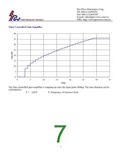
Time Controlled Gain
Amplifier
Bandwidth of 2nd Amp
R=5.6K,C=1000pF
40
-
42
KHz
KHz
Foscr
GR
0.001
500
29
-1
34
150
-
30
0
35
170
20
-20
0.3
0.2
0.9
0.05
31
+1
36
200
40
-80
0.4
-
dB
dB
dB
KHz
mA
Min(1x, 0dB)
Max(58x, 35.2dB)
Gain = 50dB
Driver_O
TCGain
GRbw
Idrv
Isink
I_OVIH
I_OVIL
I_OVOH
I_OVOL
Driving Current
Driver_O
-
-
Vcc
Vcc
Input Voltage Level
Output Voltage Level
0.15
-
0
1
-
Input Low Level
Current
I_O Internal Pull Up
Resistance
I_OIOL
Rup
-
-10
5
-20
6.5
mA
3.5
KΩ
Absolute Maximum Ratings
Description
Symbol
Vcc
Condition
Min.
0
Max.
12
Unit
V
Supply Voltage
℃
Operation Temperature
Topr
Tstg
-40
-65
-0.3
-0.3
-10
+85
℃
Storage Temperature
Max. Pin Input Voltage
Max. Input Current
+150
Vcc+0.3
Vreg+0.3
+10
I_O,Vcc
Others
*
V
Vimax
Iimax
mA
*To prevent latch up, the instantaneous input current should be no large than 100mA for each pins.
3

 ETC [ ETC ]