Pro-Wave Electronics Corp.
Tel: 886-2-22465101
Fax: 886-2-22465105
E-mail: sales@pro-wave.com.tw
URL: http://www.prowave.com.tw
Application Note
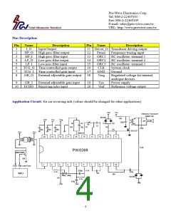
The circuit shown on page 4 is a typical circuit for car reversing aids. The RC Oscillator generates a tone burst
when a low level pulse is applied to the I_O pin, (pin 1).
To accommodate tolerance variations of transducers during manufacturing, a 1K-ohm variable resistor (R1) is
provided to trim the output operating frequency. The range of adjustment is from 38.0 – 42.0 KHz. and allows for a
better match of the drive signal to the resonate frequency of the transducer.
The active burst number (number of pulses transmitted) is controlled by the pulse width of the low level signal
applied to the I_O pin, (pin 1).
The tone burst output, Driver_O (pin 11), drives the transducer through a MOSFET transistor and impedance
matching transformer IFT. The inductance in the secondary winding of the transformer is designed to tune out the
reactance of the parallel capacitance of the transducer.
The high output voltage of the tone burst is snubbed by two diodes and the returning echo signal is passed on to the
first stage pre-amplifier. The signal is then passed on to the second stage fix gain amplifier and finally to the third
stage 32-step time controlled variable gain amplifier. The gain of the pre-amplifier should be properly set to meet
the sensitivity needs of the transducer and application requirements.
The center frequency of band-pass filter should be chosen to exactly match the frequency of the RC Oscillator and
considerations for the width of pass-band filter should be made based on actual application requirements.
If the amplified echo signal from the output of the band pass filter exceeds 0.35V + Vref, the comparator will
output a low pulse to the I_O pin, (pin 1). The width of the low level pulse is proportional to the echo signal
strength.
The above description is summarized in the signal timing charts illustrated below.
MCU output: H: 1ms/Div., V: 2.0V/Div.
The RC oscillator will be enabled in the
duration of input pulse. The maximum
pulse width is 396/F and any time longer
than this upper limit will be ignored.
Driver_O (Pin 11): H: 1ms/Div., V: 2.0V/Div.
Transducer Oscillation: H: 1ms/Div., V: 50V/Div.
HP_O (Pin 2): H: 1ms/Div., V: 2.0V/Div.
The next input pulse will be ignored if
the pulse repetition rate is shorter than
9900/F + pulse width.
F: Frequency of system clock
Output at Pin 1 I_O: H: 1ms/Div., V: 5.0V/Div.
5

 ETC [ ETC ]