ICL8052A/ICL71C03, ICL8068A/ICL71C03
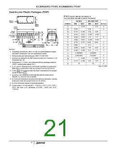
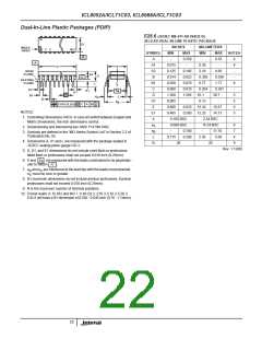
Dual-In-Line Plastic Packages (PDIP)
E28.6 (JEDEC MS-011-AB ISSUE B)
N
28 LEAD DUAL-IN-LINE PLASTIC PACKAGE
E1
INCHES
MILLIMETERS
INDEX
AREA
1
2
3
N/2
SYMBOL
MIN
MAX
0.250
-
MIN
-
MAX
6.35
-
NOTES
-B-
A
A1
A2
B
-
4
-A-
0.015
0.125
0.014
0.030
0.008
1.380
0.005
0.600
0.485
0.39
3.18
0.356
0.77
0.204
4
D
E
0.195
0.022
0.070
0.015
1.565
-
4.95
0.558
1.77
0.381
39.7
-
-
BASE
PLANE
A2
A
-C-
-
SEATING
PLANE
B1
C
8
L
C
L
-
D1
B1
eA
A1
A
D1
e
D
35.1
5
eC
B S
C
B
D1
E
0.13
15.24
12.32
5
eB
0.010 (0.25) M
C
0.625
0.580
15.87
14.73
6
NOTES:
E1
e
5
1. Controlling Dimensions: INCH. In case of conflict between English and
Metric dimensions, the inch dimensions control.
0.100 BSC
0.600 BSC
2.54 BSC
15.24 BSC
-
e
e
6
A
2. Dimensioning and tolerancing per ANSI Y14.5M-1982.
-
0.700
0.200
-
17.78
5.08
7
B
3. Symbols are defined in the “MO Series Symbol List” in Section 2.2 of
Publication No. 95.
L
0.115
2.93
4
9
4. Dimensions A, A1 and L are measured with the package seated in
N
28
28
JEDEC seating plane gauge GS-3.
Rev. 1 12/00
5. D, D1, and E1 dimensions do not include mold flash or protrusions.
Mold flash or protrusions shall not exceed 0.010 inch (0.25mm).
e
6. E and
are measured with the leads constrained to be perpendic-
A
-C-
ular to datum
.
7. e and e are measured at the lead tips with the leads unconstrained.
B
C
e
must be zero or greater.
C
8. B1 maximum dimensions do not include dambar protrusions. Dambar
protrusions shall not exceed 0.010 inch (0.25mm).
9. N is the maximum number of terminal positions.
10. Corner leads (1, N, N/2 and N/2 + 1) for E8.3, E16.3, E18.3, E28.3,
E42.6 will have a B1 dimension of 0.030 - 0.045 inch (0.76 - 1.14mm).
22

 ETC [ ETC ]