ICL8052A/ICL71C03, ICL8068A/ICL71C03
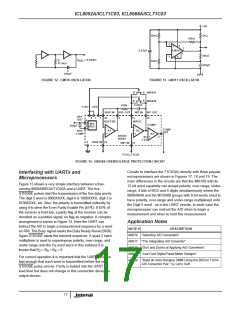
+5V
16kΩ
1kΩ
56kΩ
2
3
8
+
7
0.22µF
LM311
1
-
30kΩ
4
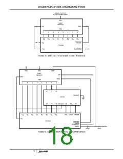
f
= 0.45/RC
R
OSC
16kΩ
37.5kΩ
390pF
C
100pF
FIGURE 12. CMOS OSCILLATOR
FIGURE 13. LM311 OSCILLATOR
D
D
S
S
2N5461
2N5458
0.22µF
100K
+15V -15V
-BUF IN BUF OUT -INT IN INT OUT
REF
OUT
8
7
1
10
BUFFER
9
11
INTEG.
14
COMP.
6
3
INT.
REF.
300pF
-
-
COMP
OUT
A1
+
A2
-
REF
COMP
+
A3
8052A/
8068A
2
+
-1.2V
5
+BUF IN 13
+INT IN 12
TO ICL71C03
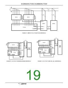
FIGURE 14. GROSS OVERVOLTAGE PROTECTION CIRCUIT
Circuits to interface the 71C03(A) directly with three popular
microprocessors are shown in Figures 17, 18 and 19. The
main differences in the circuits are that the IM6100 with its
12-bit word capability can accept polarity, over-range, under-
range, 4 bits of BCD and 5 digits simultaneously where the
8080/8048 and the MC6800 groups with 8-bit words need to
have polarity, over-range and under-range multiplexed onto
the Digit 5 word - as in the UART circuits. In each case the
microprocessor can instruct the A/D when to begin a
measurement and when to hold this measurement.
Interfacing with UARTs and
Microprocessors
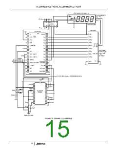
Figure 15 shows a very simple interface between a free-
running 8068A/8052A/71C03A and a UART. The five
STROBE pulses start the transmission of the five data words.
The digit 5 word is 0000XXXX, digit 4 is 1000XXXX, digit 3 is
0100XXXX, etc. Also, the polarity is transmitted indirectly by
using it to drive the Even Parity Enable Pin (EPE). If EPE of
the receiver is held low, a parity flag at the receiver can be
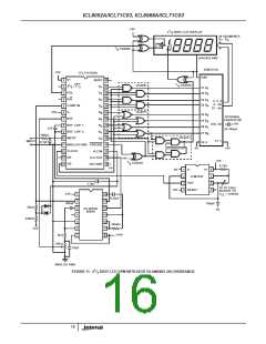
decoded as a positive signal, no flag as negative. A complex
arrangement is shown in Figure 14. Here the UART can
instruct the A/D to begin a measurement sequence by a word
on RRI. The Busy signal resets the Data Ready Reset (DRR).
Again STROBE starts the transmit sequence. A quad 2 input
multiplexer is used to superimpose polarity, over-range, and
Application Notes
NOTE #
DESCRIPTION
AN016 “Selecting A/D Converters”
AN017 “The Integrating A/D Converter”
AN018 “Do’s and Don’ts of Applying A/D Converters”
AN023 “Low Cost Digital Panel Meter Designs”
under-range onto the D word since in this instance it is
5
known that B = B = B = 0.
2
4
8
For correct operation it is important that the UART clock be
fast enough that each word is transmitted before the next
STROBE pulse arrives. Parity is locked into the UART at
load time but does not change in this connection during an
output stream.
AN028 “Build an Auto-Ranging DMM Using the 8052A/7103A
A/D Converter Pair,” by Larry Goff
17

 ETC [ ETC ]