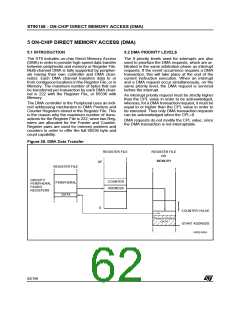
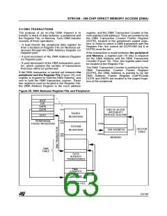
ST90158 - INTERRUPTS
INTERRUPT REGISTERS (Cont’d)
EXTERNAL INTERRUPT VECTOR REGISTER
(EIVR)
NESTED INTERRUPT CONTROL (NICR)
R247 - Read/Write
Register Page: 0
Reset value: 0000 0000 (00h)
R246 - Read/Write
Register Page: 0
Reset value: xxxx 0110b (x6h)
7
0
7
0
TLNM HL6 HL5 HL4 HL3 HL2 HL1 HL0
V7
V6
V5
V4 TLTEV TLIS IAOS EWEN
Bit 7 = TLNM: Top Level Not Maskable.
This bit is set by software and cleared only by a
hardware reset.
0: Top Level Interrupt Maskable. A top level re-
quest is generated if the IEN, TLI and TLIP bits
=1
Bit 7:4 = V[7:4]: Most significant nibble of External
Interrupt Vector.
These bits are not initialized by reset. For a repre-
sentation of how the full vector is generated from
V[7:4] and the selected external interrupt channel,
refer to Figure 26.
1: Top Level Interrupt Not Maskable. A top level
request is generated if the TLIP bit =1
Bit 3 = TLTEV: Top Level Trigger Event bit.
This bit is set and cleared by software.
0: Select falling edge as NMI trigger event
1: Select rising edge as NMI trigger event
Bit 6:0 = HL[6:0]: Hold Level x
These bits are set by hardware when, in Nested
Mode, an interrupt service routine at level x is in-
terrupted from a request with higher priority (other
than the Top Level interrupt request). They are
cleared by hardware at the iretexecution when
the routine at level x is recovered.
Bit 2 = TLIS: Top Level Input Selection.
This bit is set and cleared by software.
0: Watchdog End of Count is TL interrupt source
1: NMI is TL interrupt source
Bit 1 = IA0S: Interrupt Channel A0 Selection.
This bit is set and cleared by software.
0: Watchdog End of Count is INTA0 source
1: External Interrupt pin is INTA0 source
Bit 0 = EWEN: External Wait Enable.
This bit is set and cleared by software.
0: WAITN pin disabled
1: WAITN pin enabled (to stretch the external
memory access cycle).
Note: For more details on Wait mode refer to the
section describing the WAITN pin in the External
Memory Chapter.
61/199
9

 ETC [ ETC ]