ST90158 - DEVICE ARCHITECTURE
SYSTEM REGISTERS (Cont’d)
POINTER 0 REGISTER (RP0)
R232 - Read/Write
Register Group: E (System)
POINTER 1 REGISTER (RP1)
R233 - Read/Write
Register Group: E (System)
Reset Value: xxxx xx00 (xxh)
Reset Value: xxxx xx00 (xxh)
7
0
0
7
0
0
RG4 RG3 RG2 RG1 RG0 RPS
0
RG4 RG3 RG2 RG1 RG0 RPS
0
Bits 7:3 = RG[4:0]: Register Group number.
This register is only used in the twin register point-
ing mode. When using the single register pointing
mode, or when using only one of the twin register
groups, the RP1 register must be considered as
RESERVED and may NOT be used as a general
purpose register.
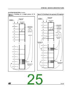
These bits contain the number (in the range 0 to
31) of the register block specified in the srp0 or
srp instructions. In single 16-register mode the
number indicates the lower of the two 8-register
blocks to which the 16 working registers are to be
mapped, while in twin 8-register mode it indicates
the 8-register block to which r0 to r7 are to be
mapped.
Bits 7:3 = RG[4:0]: Register Group number.
These bits contain the number (in the range 0 to
31) of the 8-register block specified in the srp1in-
struction, to which r8to r15are to be mapped.
Bit 2 = RPS: Register Pointer Selector.
This bit is set by the instructions srp0and srp1to
indicate that the twin register pointing mode is se-
lected. The bit is reset by the srpinstruction to in-
dicate that the single register pointing mode is se-
lected.
Bit 2 = RPS: Register Pointer Selector.
This bit is set by the srp0and srp1instructions to
indicate that the twin register pointing mode is se-
lected. The bit is reset by the srpinstruction to in-
dicate that the single register pointing mode is se-
lected.
0: Single register pointing mode
1: Twin register pointing mode
0: Single register pointing mode
1: Twin register pointing mode
Bits 1:0: Reserved. Forced by hardware to zero.
Bits 1:0: Reserved. Forced by hardware to zero.
24/199
9

 ETC [ ETC ]