ST90158 - DEVICE ARCHITECTURE
MEMORY SPACES (Cont’d)
2.2.2 Register Addressing
Therefore if the Page Pointer, R234, is set to 5, the
instructions:
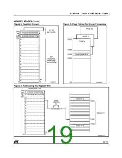
Register File registers, including Group F paged
registers (but excluding Group D), may be ad-
dressed explicitly by means of a decimal, hexa-
decimal or binary address; thus R231, RE7hand
R11100111b represent the same register (see
Figure 8). Group D registers can only be ad-
dressed in Working Register mode.
spp #5
ld R242, r4
will load the contents of working register r4 into the
third register of page 5 (R242).
These paged registers hold data and control infor-
mation relating to the on-chip peripherals, each
peripheral always being associated with the same
pages and registers to ensure code compatibility
between ST9 devices. The number of these regis-
ters therefore depends on the peripherals which
are present in the specific ST9 family device. In
other words, pages only exist if the relevant pe-
ripheral is present.
Note that an upper case “R” is used to denote this
direct addressing mode.
Working Registers
Certain types of instruction require that registers
be specified in the form “rx”, where x is in the
range 0 to 15: these are known as Working Regis-
ters.
Note that a lower case “r” is used to denote this in-
direct addressing mode.
Table 3. Register File Organization
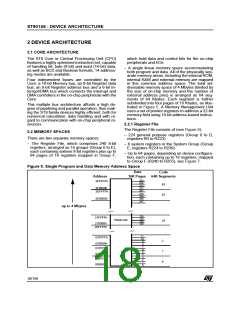
Two addressing schemes are available: a single
group of 16 working registers, or two separately
mapped groups, each consisting of 8 working reg-
isters. These groups may be mapped starting at
any 8 or 16 byte boundary in the register file by
means of dedicated pointer registers. This tech-
nique is described in more detail in Section 2.3.3
Register Pointing Techniques, and illustrated in
Figure 9 and in Figure 10.
Hex.
Address
Decimal
Address
Register
File Group
Function
Paged
Registers
F0-FF
E0-EF
240-255
224-239
Group F
Group E
System
Registers
D0-DF
C0-CF
B0-BF
A0-AF
90-9F
80-8F
70-7F
60-6F
50-5F
40-4F
30-3F
20-2F
10-1F
00-0F
208-223
192-207
176-191
160-175
144-159
128-143
112-127
96-111
80-95
Group D
Group C
Group B
Group A
Group 9
Group 8
Group 7
Group 6
Group 5
Group 4
Group 3
Group 2
Group 1
Group 0
System Registers
The 16 registers in Group E (R224 to R239) are
System registers and may be addressed using any
of the register addressing modes. These registers
are described in greater detail in Section 2.3 SYS-
TEM REGISTERS.
General
Purpose
Registers
Paged Registers
Up to 64 pages, each containing 16 registers, may
be mapped to Group F. These are addressed us-
ing any register addressing mode, in conjunction
with the Page Pointer register, R234, which is one
of the System registers. This register selects the
page to be mapped to Group F and, once set,
does not need to be changed if two or more regis-
ters on the same page are to be addressed in suc-
cession.
64-79
48-63
32-47
16-31
00-15
20/199
9

 ETC [ ETC ]