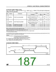
ST90158 - ELECTRICAL CHARACTERISTICS
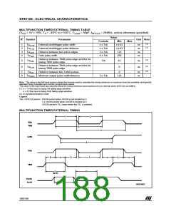
MULTIFUNCTION TIMER EXTERNAL TIMING TABLE
(V = 5V ± 10%, T = –40°C to +105°C, C
= 50pF, f = 24MHz, unless otherwise specified)
DD
A
Load
INTCLK
Value
N° Symbol
Parameter
Unit Note
Formula
Min
n x 42
n x 42
125
Max
(1)
(1)
1
2
3
4
Tw
External clock/trigger pulse width
External clock/trigger pulse distance
Distance between two active edges
Gate pulse width
n x Tck
n x Tck
3 x Tck
6 x Tck
-
-
-
-
ns
ns
ns
ns
CTW
Tw
Tw
CTD
AED
Tw
250
GW
LBA
Distance between TINB pulse edge and the fol-
lowing TINA pulse edge
(2)
5
6
Tw
Tck
42
0
-
-
ns
ns
Distance between TINA pulse edge and the fol-
lowing TINB pulse edge
(2)
(2)
Tw
LAB
7
8
Tw
Distance between two TxINA pulses
Minimum output pulse width/distance
0
-
-
ns
ns
AD
Tw
3 x Tck
125
OWD
Note: The value in the left hand column shows the formula used to calculate the timing minimum or maximum from the oscillator clock period,
standard timer prescaler and counter programmed values.
The value in the right hand two columns show the timing minimum and maximum for an internal clock (INTCLK) at 24MHz.
(1) n = 1 if the input is rising OR falling edge sensitive
n = 3 if the input is rising AND falling edge sensitive
(2) In Autodiscrimination mode
Legend:
Tck = INTCLK period = OSCIN period when OSCIN is not divided by 2;
2 x OSCIN period when OSCIN is divided by 2;
OSCIN period x PLL factor when the PLL is enabled.
MULTIFUNCTION TIMER EXTERNAL TIMING
188/199
1

 ETC [ ETC ]