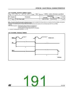
ST90158 - ELECTRICAL CHARACTERISTICS
STANDARD TIMER TIMING TABLE
(V = 5V ± 10%, T = –40°C to +105°C, C
unless otherwise specified)
= 50pF, f = 24MHz, Push-pull output configuration,
INTCLK
DD
A
Load
Value
N°
Symbol
Parameter
Unit
(1)
Formula
Min
Max
167
ns
s
4 x (Psc+1) x (Cnt+1) x Tck
(Psc+1) x (Cnt+1) x T
2.8
(2)
1
TwSTOL
STOUT Low Pulse Width
STIN
(2)
ns
with T
≥ 8 x Tck
STIN
167
ns
s
4 x (Psc+1) x (Cnt+1) x Tck
(Psc+1) x (Cnt+1) x T
2.8
(2)
2
TwSTOH
STOUT High Pulse Width
STIN
(2)
ns
with T
≥ 8 x Tck
STIN
3
4
TwSTIL
TwSTIH
STIN High Pulse Width
STIN Low Pulse Width
≥ 4 x Tck
≥ 4 x Tck
(2)
(2)
(2)
(2)
ns
ns
Note: The value in the left hand column shows the formula used to calculate the timing minimum or maximum from the oscillator clock period,
standard timer prescaler and counter programmed values.
The value in the right hand two columns show the timing minimum and maximum for an internal clock (INTCLK) at 24MHz, with minimum and
maximum prescaler value and minimum and maximum counter value.
Measurement points are V
or V for positive pulses and V or V for negative pulses.
IH OL IL
OH
(1) Formula guaranteed by design.
(2) Onthis product STIN isnot availableas Alternate Functionbut itis internallyconnectedtoa preciseclocksourcedirectly derivedfromOSCIN.
Refer to RCCU chapter for details about clock distribution.
Legend:
Tck = INTCLK period = OSCIN period when OSCIN is not divided by 2;
2 x OSCIN period when OSCIN is divided by 2;
OSCIN period x PLL factor when the PLL is enabled.
Psc = Standard Timer Prescaler Register content (STP): from 0 to 255
Cnt = Standard Timer Couter Registers content (STH,STL): from 0 to 65535
T
= Standard Timer Input signal period (STIN).
STIN
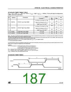
STANDARD TIMER TIMING
187/199
1

 ETC [ ETC ]