ST90158 - ELECTRICAL CHARACTERISTICS
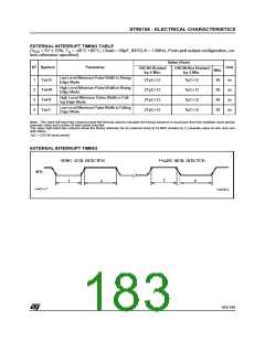
EXTERNAL INTERRUPT TIMING TABLE
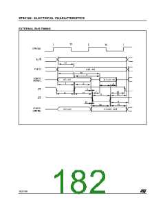
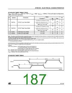
(V = 5V ± 10%, T = -40°C +85°C, Cload = 50pF, INTCLK = 12MHz, Push-pull output configuration, un-
DD
A
less otherwise specified)
Value (Note)
OSCIN Not Divided
N° Symbol
Parameter
Unit
OSCIN Divided
by 2 Min.
Min.
95
by 2 Min.
Low Level Minimum Pulse Width in Rising
Edge Mode
1
2
3
4
TwLR
TwHR
TwHF
TwLF
2TpC+12
2TpC+12
2TpC+12
2TpC+12
TpC+12
ns
ns
ns
ns
High Level Minimum Pulse Width in Rising
Edge Mode
TpC+12
TpC+12
TpC+12
95
High Level Minimum Pulse Width in Fall-
ing Edge Mode
95
Low Level Minimum Pulse Width in Falling
Edge Mode
95
Note: The value left hand two columns show the formula used to calculate the timing minimum or maximum from the oscillator clock period,
prescale value and number of wait cycles inserted.
The value right hand two columns show the timing minimum for an external clock at 24 MHz divided by 2, prescale value of zero and zero
wait status.
TpC = OSCIN clock period
EXTERNAL INTERRUPT TIMING
183/199
9

 ETC [ ETC ]