ST6200C/ST6201C/ST6203C
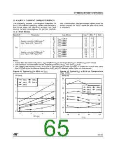
SUPPLY CURRENT CHARACTERISTICS (Cont’d)
11.4.3 STOP Mode
1)
Symbol
Parameter
Conditions
Typ
Max
Unit
3)
10
20
OTP devices
ROM devices
0.3
4)
2)
Supply current in STOP mode
(see Figure 47 & Figure 48)
I
µA
DD
3)
2
20
0.1
4)
Notes:
1. Typical data are based on V =5.0V at T =25°C.
DD
A
2. All I/O pins in input with pull-up mode (no load), all peripherals in reset state, OSG and LVD disabled, option bytes
programmed to 00H. Data based on characterization results, tested in production at V max. and f
max.
DD
CPU
3. Maximum STOP consumption for -40°C<Ta<90°C
4. Maximum STOP consumption for -40°C<Ta<125°C
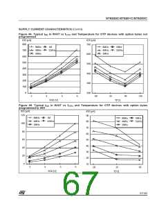
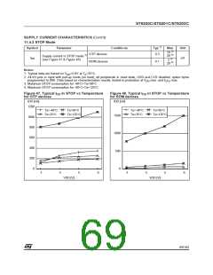
Figure 47. Typical I in STOP vs Temperature
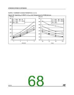
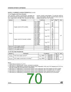
Figure 48. Typical I in STOP vs Temperature
DD
DD
for OTP devices
for ROM devices
IDD [nA]
IDD [nA]
1200
Ta=-40°C
Ta=25°C
Ta=95°C
Ta=-40°C
Ta=25°C
Ta=95°C
Ta=125°C
Ta=125°C
1500
1000
500
0
1000
800
600
400
200
0
3
4
5
6
3
4
5
6
VDD [V]
VDD [V]
69/104
1

 ETC [ ETC ]