RTL8211C & RTL8211CL
Datasheet
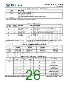
Pin
LINK Bit
Active (Tx/Rx) Bit
Description
10
1
100
0
1000
1
1
0
0
1
1
0
1
0
1
0
1
Link 10/1000
Link 10/1000+Active
Link 10/100
1
0
1
1
1
1
Link 10/100+Active
Link 10/100/1000
Link (10/10/1000)+Active
1
1
1
1
6.9. Polarity Correction
The RTL8211C(L) automatically corrects polarity errors on the receive pairs in 1000Base-T and 10Base-T
modes. In 100Base-TX mode polarity is irrelevant. In 1000Base-T mode, receive polarity errors are
automatically corrected based on the sequence of idle symbols. Once the descrambler is locked, the polarity
is also locked on all pairs. The polarity becomes unlocked only when the receiver loses lock. In 10Base-T
mode, polarity errors are corrected based on the detection of validly spaced link pulses. The detection
begins during the MDI crossover detection phase and locks when the 10Base-T link is up. The polarity
becomes unlocked when the link is down.
6.10. Power
The RTL8211C(L) implements a voltage regulator to generate operating power. The system vendor needs
to supply a 3.3V, 1A steady power source. The RTL8211C(L) converts the 3.3V steady power source to
1.05V via a switching regulator.
Another possible implementation is to use an external regulator to generate 1.0V. Be sure that the regulator
meets the required current rate.
The RTL8211C(L) implements an option for the RGMII power pins. The standard I/O voltage of the
RGMII interface is 3.3V, with support for 2.5V to lower EMI. The 2.5V power source for RGMII is from an
external regulator.
Integrated 10/100/1000 Gigabit Ethernet Transceiver
21
Track ID: JATR-1076-21 Rev. 1.3

 ETC [ ETC ]