a-Si TFT LCD Single Chip Driver
240RGBx320 Resolution and 262K color
ILI9325
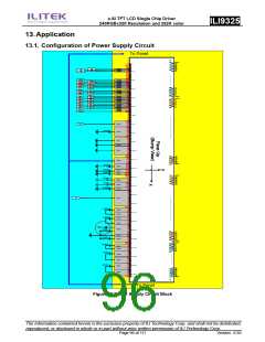
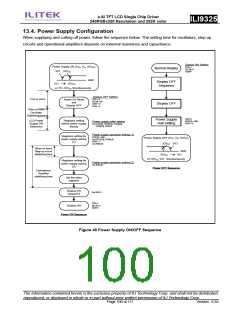
13.4. Power Supply Configuration
When supplying and cutting off power, follow the sequence below. The setting time for oscillators, step-up
circuits and operational amplifiers depends on external resistance and capacitance.
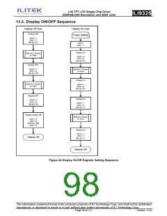
Display ON Setting
Power Supply ON (VCC, VCI, IOVCC
VCI IOVCC
)
DTE=1
Normal Display
D[1:0]=11
GON=1
GND
Display OFF
Sequence
VCI
IOVCC
or VCI, IOVCC Simultaneously
Display OFF Setting
DTE = 0
1ms or more
Power On Reset
and
Display OFF
D[1:0] = 00
GON = 0
PON = 0
Display OFF
10ms or more
Oscillator
Stabilizing time
SAP=0
AP[2:0] = 000
PON = 0
Power Supply
Halt Setting
LCD Power
Supply ON
Sequence
Registers setting
before power supply
startup
Power supply initial setting
Set VC[2:0], VRH[3:0], VCM[5;0],
VDV[5:0], PON=0
Power supply operation setting (1)
Registers setting for
power supply startup
(1)
BT[2:0] = 000
Set DC1[2:0], DC0[2:0]
PON = 1
Power Supply OFF (VCC, VCI, IOVCC
)
IOVCC VCI
Set AP[2:0]
40ms or more
Step-up circuit
stabilizing time
GND
VCI
IOVCC
Or IOVCC, VCI Simultaneously
Registers setting for
power supply startup
(2)
Power supply operation setting (2)
Set BT[2:0]
Power OFF Sequence
Operational
Amplifier
stabilizing time
Set the other
registers
Display ON
Sequence
Set SAP=1
DTE=1
D[1:0]=11
GON=1
Display ON
Power ON Sequence
Figure 46 Power Supply ON/OFF Sequence
The information contained herein is the exclusive property of ILI Technology Corp. and shall not be distributed,
reproduced, or disclosed in whole or in part without prior written permission of ILI Technology Corp.
Page 100 of 111
Version: 0.35

 ETC [ ETC ]