Freescale Semiconductor, Inc.
System Setup
Executing the Application
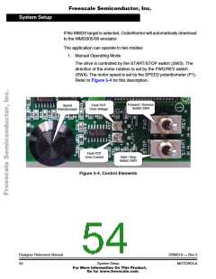
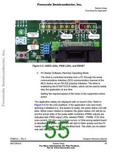
Figure 5-5. USER LEDs, PWM LEDs, and RESET
2. PC Master Software (Remote) Operating Mode
The drive is controlled remotely from a PC through the serial
communications interface (SCI) communication channel of the
MCU device via an RS-232 physical interface. The drive is
enabled by the START/STOP switch, which can be used to safely
stop the application at any time.
Setting the required speed of the motor is the supported control
action.
The application states are displayed with on-board LEDs. Refer to
Figure 5-5 for the LED positions. If the application runs and motor
spinning is disabled (i.e., the system is ready), the green status LED will
blink. When motor rotation is enabled, the green status LED will be on,
and the actual state of the pulse-width modulator (PWM) outputs are
indicated with PWM output LEDs, labeled PWM1 - PWM6. If DC-Bus
over-current / DC-Bus over-voltage occurs, or if the wrong system board
is identified, the green status LED will start to flash quickly and the PC
master software will signal the identified fault. This state can be exited
only with the application reset.
DRM019 — Rev 0
MOTOROLA
Designer Reference Manual
System Setup
55
For More Information On This Product,
Go to: www.freescale.com

 ETC [ ETC ]