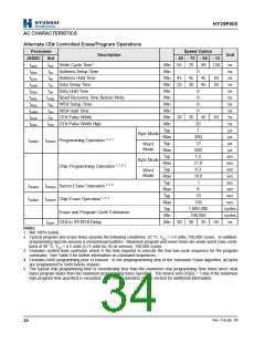
HY29F800
AC CHARACTERISTICS
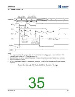
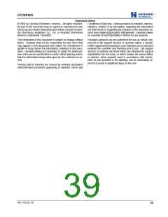
PA for Program
SA for Sector Erase
0x555 for Chip Erase
0x555 for Program
0x2AA for Erase
Addresses
VA
tW C
tAS
tAH
WE#
OE#
CE#
tGHEL
tW H
tCP
tCPH
tW H W H 1 or tW H W H 2 or tW H W H 3
tW S
tDS
tDH
tBUSY
Data
Status
D OUT
0xA0 for Program
0x55 for Erase
PD for Program
0x30 for Sector Erase
0x10 for Chip Erase
RY/BY#
tRH
RESET#
Notes:
1. PA = program address, PD = program data, VA = Valid Address for reading program or erase status (see Write
Operation Status section), DOUT = array data read at VA.
2. Illustration shows the last two cycles of the program or erase command sequence and the last status read cycle.
3. Word mode addressing shown.
4. RESET# shown only to illustrate tRH measurement references. It cannot occur as shown during a valid command
sequence.
Figure 25. Alternate CE# Controlled Write Operation Timings
Rev. 4.0/Jan. 00
35

 ETC [ ETC ]